
Page 62 - Handbook of Civil Engineering Calculations, Second Edition
P. 62
STATICS, STRESS AND STRAIN, AND FLEXURAL ANALYSIS 1.45
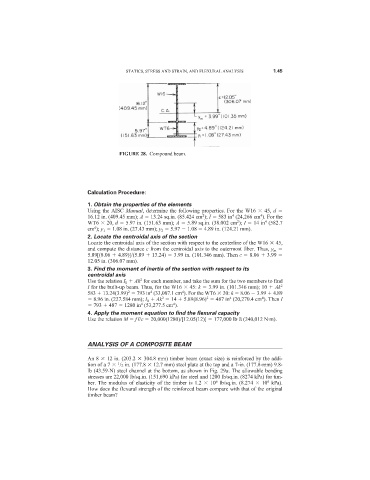
FIGURE 28. Compound beam.
Calculation Procedure:
1. Obtain the properties of the elements
Using the AISC Manual, determine the following properties. For the W16 45, d
2
4
4
16.12 in. (409.45 mm); A 13.24 sq.in. (85.424 cm ); I 583 in (24,266 cm ). For the
4
2
WT6 20, d 5.97 in. (151.63 mm); A 5.89 sq.in. (38.002 cm ); I 14 in (582.7
4
cm ); y 1 1.08 in. (27.43 mm); y 2 5.97 1.08 4.89 in. (124.21 mm).
2. Locate the centroidal axis of the section
Locate the centroidal axis of the section with respect to the centerline of the W16 45,
and compute the distance c from the centroidal axis to the outermost fiber. Thus, y m
5.89[(8.06 4.89)]/(5.89 13.24) 3.99 in. (101.346 mm). Then c 8.06 3.99
12.05 in. (306.07 mm).
3. Find the moment of inertia of the section with respect to its
centroidal axis
2
Use the relation I 0 Ak for each member, and take the sum for the two members to find
I for the built-up beam. Thus, for the W16 45: k 3.99 in. (101.346 mm); 10 Ak 2
2
4
4
583 13.24(3.99) 793 in (33,007.1 cm ). For the WT6 20: k 8.06 3.99 4.89
2
4
4
2
8.96 in. (227.584 mm); I 0 Ak 14 5.89(8.96) 487 in (20,270.4 cm ). Then I
4
4
793 487 1280 in (53,277.5 cm ).
4. Apply the moment equation to find the flexural capacity
Use the relation M fI/c 20,000(1280)/[12.05(12)] 177,000 lb·ft (240,012 N·m).
ANALYSIS OF A COMPOSITE BEAM
An 8 12 in. (203.2 304.8 mm) timber beam (exact size) is reinforced by the addi-
tion of a 7 /2 in. (177.8 12.7 mm) steel plate at the top and a 7-in. (177.8-mm) 9.8-
1
lb (43.59-N) steel channel at the bottom, as shown in Fig. 29a. The allowable bending
stresses are 22,000 lb/sq.in. (151,690 kPa) for steel and 1200 lb/sq.in. (8274 kPa) for tim-
6
6
ber. The modulus of elasticity of the timber is 1.2 10 lb/sq.in. (8.274 10 kPa).
How does the flexural strength of the reinforced beam compare with that of the original
timber beam?