
Page 57 - Handbook of Civil Engineering Calculations, Second Edition
P. 57
1.40 STRUCTURAL STEEL ENGINEERING AND DESIGN
Calculation Procedure:
1. Determine the relationship
between the torque in the shaft
segments
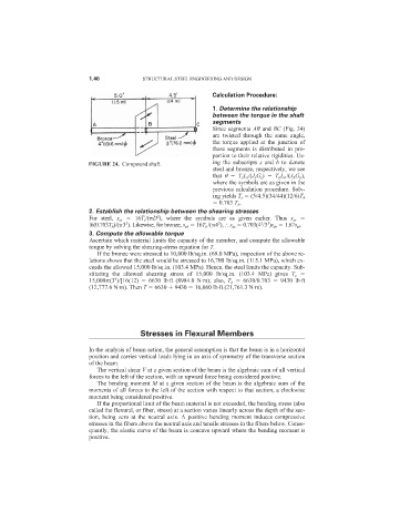
Since segments AB and BC (Fig. 24)
are twisted through the same angle,
the torque applied at the junction of
these segments is distributed in pro-
portion to their relative rigidities. Us-
FIGURE 24. Compound shaft. ing the subscripts s and b to denote
steel and bronze, respectively, we see
that T s L s /(J s G s ) T b L b /(J b G b ),
where the symbols are as given in the
previous calculation procedure. Solv-
ing yields T s (5/4.5)(34/44)(12/6)T b
0.703 T b .
2. Establish the relationship between the shearing stresses
For steel, s ss 16T s /( D ), where the symbols are as given earlier. Thus s ss
3
3
3
3
3
l6(0.703T b )/( 3 ). Likewise, for bronze, s sb 16T b /( 4 ), s ss 0.703(4 /3 )s sb 1.67s sb .
3. Compute the allowable torque
Ascertain which material limits the capacity of the member, and compute the allowable
torque by solving the shearing-stress equation for T.
If the bronze were stressed to 10,000 lb/sq.in. (69.0 MPa), inspection of the above re-
lations shows that the steel would be stressed to 16,700 lb/sq.in. (115.1 MPa), which ex-
ceeds the allowed 15,000 lb/sq.in. (103.4 MPa). Hence, the steel limits the capacity. Sub-
stituting the allowed shearing stress of 15,000 lb/sq.in. (103.4 MPa) gives T s
3
15,000 (3 )/[16(12) 6630 lb·ft (8984.0 N·m); also, T b 6630/0.703 9430 lb·ft
(12,777.6 N·m). Then T 6630 9430 16,060 lb·ft (21,761.3 N·m).
Stresses in Flexural Members
In the analysis of beam action, the general assumption is that the beam is in a horizontal
position and carries vertical loads lying in an axis of symmetry of the transverse section
of the beam.
The vertical shear V at a given section of the beam is the algebraic sum of all vertical
forces to the left of the section, with an upward force being considered positive.
The bending moment M at a given section of the beam is the algebraic sum of the
moments of all forces to the left of the section with respect to that section, a clockwise
moment being considered positive.
If the proportional limit of the beam material is not exceeded, the bending stress (also
called the flexural, or fiber, stress) at a section varies linearly across the depth of the sec-
tion, being zero at the neutral axis. A positive bending moment induces compressive
stresses in the fibers above the neutral axis and tensile stresses in the fibers below. Conse-
quently, the elastic curve of the beam is concave upward where the bending moment is
positive.