
Page 60 - Handbook of Civil Engineering Calculations, Second Edition
P. 60
STATICS, STRESS AND STRAIN, AND FLEXURAL ANALYSIS 1.43
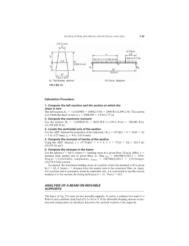
FIGURE 26
Calculation Procedure:
1. Compute the left reaction and the section at which the
shear is zero
The left reaction R L /2(10)(500) 1600(2.5/10) 2900 lb (12,899.2 N). The section
1
A at which the shear is zero is x 2900/500 5.8 ft (1.77 m).
2. Compute the maximum moment
1
Use the relation M A /2(2900)(5.8) 8410 lb·ft (11,395.6 N·m) 100,900 lb·in.
(11,399.682 N·m).
3. Locate the centroidal axis of the section
Use the AISC Manual for properties of the trapezoid. Or y t (9/3)[(2 6 3)1(6 3)]
5 in. (127 mm); y b 4 in. (101.6 mm).
4. Compute the moment of inertia of the section
2
2
3
Using the AISC Manual, I (9 /36)[(6 4 6 3 3 )/(6 3)] 263.3 in 4
4
(10,959.36 cm ).
5. Compute the stresses in the beam
Use the relation f My/I, where f bending stress in a given fiber, lb/sq.in. (kPa); y
distance from neutral axis to given fiber, in. Thus f top 100,900(5)/263.3 1916-
lb/sq.in. (13,210.8-kPa) compression, f bottom 100,900(4)/263.3 1533-lb/sq.in.
(10,570.0-kPa) tension.
In general, the maximum bending stress at a section where the moment is M is given
by f M C /I, where c distance from the neutral axis to the outermost fiber, in. (mm).
For a section that is symmetric about its centroidal axis, it is convenient to use the section
modulus S of the section, this being defined as S I/c. Then f M/S.
ANALYSIS OF A BEAM ON MOVABLE
SUPPORTS
The beam in Fig. 27a rests on two movable supports. It carries a uniform live load of w
lb/lin ft and a uniform dead load of 0.2w lb/lin ft. If the allowable bending stresses in ten-
sion and compression are identical, determine the optimal location of the supports.