Page 55 - Handbook of Civil Engineering Calculations, Second Edition
P. 55

1.38            STRUCTURAL STEEL ENGINEERING AND DESIGN

                            THERMAL EFFECTS IN COMPOSITE
                            MEMBER HAVING ELEMENTS IN SERIES

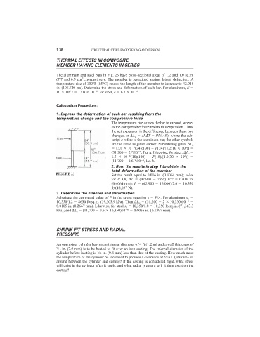
                            The aluminum and steel bars in Fig. 23 have cross-sectional areas of 1.2 and 1.0 sq.in.
                                       2
                            (7.7 and 6.5 cm ), respectively. The member is restrained against lateral deflection. A
                            temperature rise of 100°F (55°C) causes the length of the member to increase to 42.016
                            in. (106.720 cm). Determine the stress and deformation of each bar. For aluminum, E
                                  6
                                                                 6
                                              6
                            10   10 c   13.0   10 ; for steel, c   6.5   10 .
                            Calculation Procedure:
                            1. Express the deformation of each bar resulting from the
                            temperature change and the compressive force
                                                     The temperature rise causes the bar to expand, where-
                                                     as the compressive force resists this expansion. Thus,
                                                     the net expansion is the difference between these two
                                                     changes, or  L a   cL T   PL/(AE), where the sub-
                                                     script a refers to the aluminum bar; the other symbols
                                                     are the same as given earlier. Substituting gives  L a
                                                       13.0   10 (24)(100)   P(24)/[1.2(10   10 )]
                                                                                        6
                                                                6
                                                                   6
                                                     (31,200   2P)10 , Eq. a. Likewise, for steel:  L s
                                                     6.5    10 (18)(100)    P(18)/[1.0(30    10 )]
                                                                                        6
                                                              6
                                                                    6
                                                     (11,700   0.6P)10 , Eq. b.
                                                     2. Sum the results in step 1 to obtain the
                                                     total deformation of the member
                           FIGURE 23                 Set the result equal to 0.016 in. (0.4064 mm); solve
                                                     for P. Or,  L   (42,900   2.6P)10  6    0.016 in.
                                                     (0.4064 mm); P   (42,900   16,000)/2.6   10,350
                                                     lb (46,037 N).
                            3. Determine the stresses and deformation
                            Substitute the computed value of P in the stress equation s   P/A. For aluminum s a
                            10,350/1.2   8630 lb/sq.in. (59,503.9 kPa). Then  L a   (31,200   2   10,350)10  6
                            0.0105 in. (0.2667 mm). Likewise, for steel s s   10,350/1.0   10,350 lb/sq.in. (71,363.3
                            kPa); and  L s   (11,700   0.6   10,350)10  6    0.0055 in. (0.1397 mm).


                            SHRINK-FIT STRESS AND RADIAL
                            PRESSURE

                            An open steel cylinder having an internal diameter of 4 ft (1.2 m) and a wall thickness of
                            5 /16 in. (7.9 mm) is to be heated to fit over an iron casting. The internal diameter of the
                                               1
                            cylinder before heating is  /32 in. (0.8 mm) less than that of the casting. How much must
                                                                              1
                            the temperature of the cylinder be increased to provide a clearance of  /32 in. (0.8 mm) all
                            around between the cylinder and casting? If the casting is considered rigid, what stress
                            will exist in the cylinder after it cools, and what radial pressure will it then exert on the
                            casting?
   50   51   52   53   54   55   56   57   58   59   60