
Page 50 - Handbook of Civil Engineering Calculations, Second Edition
P. 50
STATICS, STRESS AND STRAIN, AND FLEXURAL ANALYSIS 1.33
EVALUATION OF PRINCIPAL STRESSES
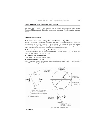
The prism ABCD in Fig. 21a is subjected to the normal and shearing stresses shown.
Construct Mohr’s circle to determine the principal stresses at A, and locate the principal
planes.
Calculation Procedure:
1. Draw the lines representing the normal stresses (Fig. 21b)
Through the origin O, draw a horizontal base line. Locate points E and F such that OE
8400 lb/sq.in. (57,918.0 kPa) and OF 2000 lb/sq.in. (13,790.0 kPa). Since both normal
stresses are tensile, E and F lie to the right of O. Note that the construction required here
is the converse of that required in the previous calculation procedure.
2. Draw the lines representing the shearing stresses
Construct the vertical lines EG and FH such that EG 3600 lb/sq.in. (24,822.0 kPa), and
FH 3600 lb/sq.in. ( 24,822.0 kPa).
3. Continue the construction
Draw line GH to intersect the base line at C.
4. Construct Mohr’s circle
Draw a circle having GH as diameter, intersecting the base line at A and B. Then lines OA
and OB represent the principal stresses.
FIGURE 21