
Page 47 - Handbook of Civil Engineering Calculations, Second Edition
P. 47
1.30 STRUCTURAL STEEL ENGINEERING AND DESIGN
the cable. Determine the sag of the cable
and the final stress in the cable. Verify that
the results obtained are compatible.
Calculation Procedure:
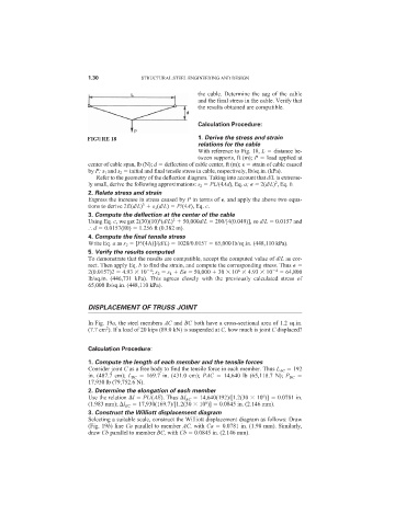
FIGURE 18 1. Derive the stress and strain
relations for the cable
With reference to Fig. 18, L distance be-
tween supports, ft (m); P load applied at
center of cable span, lb (N); d deflection of cable center, ft (m);
strain of cable caused
by P; s 1 and s 2 initial and final tensile stress in cable, respectively, lb/sq.in. (kPa).
Refer to the geometry of the deflection diagram. Taking into account that d/L is extreme-
2
ly small, derive the following approximations: s 2 PL/(4Ad), Eq. a;
2(d/L) , Eq. b.
2. Relate stress and strain
Express the increase in stress caused by P in terms of
, and apply the above two equa-
3
tions to derive 2E(d/L) s 1 (d/L) P/(4A), Eq. c.
3. Compute the deflection at the center of the cable
6
3
Using Eq. c, we get 2(30)(10) (d/L) 50,000d/L 200/[4(0.049)], so d/L 0.0157 and
d 0.0157(80) 1.256 ft (0.382 m).
4. Compute the final tensile stress
Write Eq. a as s 2 [P/(4A)]/(d/L) 1020/0.0157 65,000 lb/sq.in. (448,110 kPa).
5. Verify the results computed
To demonstrate that the results are compatible, accept the computed value of d/L as cor-
rect. Then apply Eq. b to find the strain, and compute the corresponding stress. Thus
6
4
2(0.0157)2 4.93 10 ; s 2 s 1 E
50,000 30 10 4.93 10 4 64,800
lb/sq.in. (446,731 kPa). This agrees closely with the previously calculated stress of
65,000 lb/sq.in. (448,110 kPa).
DISPLACEMENT OF TRUSS JOINT
In Fig. 19a, the steel members AC and BC both have a cross-sectional area of 1.2 sq.in.
2
(7.7 cm ). If a load of 20 kips (89.0 kN) is suspended at C, how much is joint C displaced?
Calculation Procedure:
1. Compute the length of each member and the tensile forces
Consider joint C as a free body to find the tensile force in each member. Thus L AC 192
in. (487.7 cm); L BC 169.7 in. (431.0 cm); PAC 14,640 lb (65,118.7 N); P BC
17,930 lb (79,752.6 N).
2. Determine the elongation of each member
6
Use the relation l PL/(AE). Thus l AC 14,640(192)/[1.2(30 10 )] 0.0781 in.
6
(1.983 mm); l BC 17,930(169.7)/[1.2(30 10 )] 0.0845 in. (2.146 mm).
3. Construct the Williott displacement diagram
Selecting a suitable scale, construct the Williott displacement diagram as follows: Draw
(Fig. 19b) line Ca parallel to member AC, with Ca 0.0781 in. (1.98 mm). Similarly,
draw Cb parallel to member BC, with Cb 0.0845 in. (2.146 mm).