
Page 45 - Handbook of Civil Engineering Calculations, Second Edition
P. 45
1.28 STRUCTURAL STEEL ENGINEERING AND DESIGN
FIGURE 16
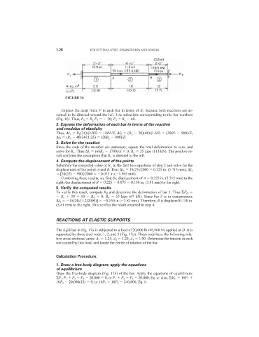
Express the axial force P in each bar in terms of R L because both reactions are as-
sumed to be directed toward the left. Use subscripts corresponding to the bar numbers
(Fig. 16). Thus, P 1 R L P 2 30; P 3 R L 40.
2. Express the deformation of each bar in terms of the reaction
and modulus of elasticity
Thus, l 1 R L (36)/(2.0E) 18RL/E; l 2 (R L 30)(48)/(1.6E) (30RL 900)/E;
l 3 (R L 40)24/(1.2E) (20R L 800)/E.
3. Solve for the reaction
Since the ends of the member are stationary, equate the total deformation to zero, and
solve for R L . Thus l t (68R L 1700)/E 0; R L 25 kips (111 kN). The positive re-
sult confirms the assumption that R L is directed to the left.
4. Compute the displacement of the points
Substitute the computed value of R L in the first two equations of step 2 and solve for the
displacement of the points A and B. Thus l 1 18(25)/2000 0.225 in. (5.715 mm); l 2
[30(25) 900]/2000 0.075 in ( 1.905 mm).
Combining these results, we find the displacement of A 0.225 in. (5.715 mm) to the
right; the displacement of B 0.225 0.075 0.150 in. (3.81 mm) to the right.
5. Verify the computed results
To verify this result, compute R R and determine the deformation of bar 3. Thus F H
R L 30 10 R R 0; R R 15 kips (67 kN). Since bar 3 is in compression,
l 3 15(24)/[1.2(2000)] 0.150 in ( 3.81 mm). Therefore, B is displaced 0.150 in.
(3.81 mm) to the right. This verifies the result obtained in step 4.
REACTIONS AT ELASTIC SUPPORTS
The rigid bar in Fig. 17a is subjected to a load of 20,000 lb (88,960 N) applied at D. It is
supported by three steel rods, 1, 2, and 3 (Fig. 17a). These rods have the following rela-
tive cross-sectional areas: A 1 1.25, A 2 1.20, A 3 1.00. Determine the tension in each
rod caused by this load, and locate the center of rotation of the bar.
Calculation Procedure:
1. Draw a free-body diagram; apply the equations
of equilibrium
Draw the free-body diagram (Fig. 17b) of the bar. Apply the equations of equilibrium:
F V P 1 P 2 P 3 20,000 0, or P 1 P 2 P 3 20,000, Eq. a; also, M C 16P 1
10P 2 20,000(12) 0, or 16P 1 10P 2 240,000, Eq. b.