
Page 48 - Handbook of Civil Engineering Calculations, Second Edition
P. 48
STATICS, STRESS AND STRAIN, AND FLEXURAL ANALYSIS 1.31
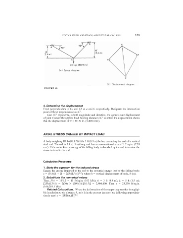
FIGURE 19
4. Determine the displacement
Erect perpendiculars to Ca and Cb at a and b, respectively. Designate the intersection
point of these perpendiculars as C
.
Line CC
represents, in both magnitude and direction, the approximate displacement
of joint C under the applied load. Scaling distance CC
to obtain the displacement shows
that the displacement of C 0.134 in. (3.4036 mm).
AXIAL STRESS CAUSED BY IMPACT LOAD
A body weighing 18 lb (80.1 N) falls 3 ft (0.9 m) before contacting the end of a vertical
steel rod. The rod is 5 ft (1.5 m) long and has a cross-sectional area of 1.2 sq.in. (7.74
2
cm ). If the entire kinetic energy of the falling body is absorbed by the rod, determine the
stress induced in the rod.
Calculation Procedure:
1. State the equation for the induced stress
Equate the energy imparted to the rod to the potential energy lost by the falling body:
0.5
s (P/A){1 [1 2Eh/(LP/A)] ), where h vertical displacement of body, ft (m).
2. Substitute the numerical values
Thus, P/A 18/1.2 15 lb/sq.in. (103 kPa); h 3 ft (0.9 m); L 5 ft (1.5 m);
6
[2Eh/(LP/A) 2(30) (10 )(3)]/[5(15)] 2,400,000. Then s 23,250 lb/sq.in.
(160,285.5 kPa).
Related Calculations. Where the deformation of the supporting member is negligi-
ble in relation to the distance h, as it is in the present instance, the following approxima-
0.5
tion is used: s [2PEh/(AL)] .