
Page 46 - Handbook of Civil Engineering Calculations, Second Edition
P. 46
STATICS, STRESS AND STRAIN, AND FLEXURAL ANALYSIS 1.29
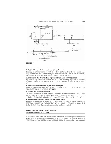
FIGURE 17
2. Establish the relations between the deformations
Selecting an arbitrary center of rotation O, show the bar in its deflected position (Fig.
17c). Establish the relationships among the three deformations. Thus, by similar triangles,
( l 1 l 2 )/( l 2 l 3 ) 6/10, or 10 l 1 16 l 2 6 l 3 0, Eq. c.
3. Transform the deformation equation to an axial-force equation
By substituting axial-force relations in Eq. c, the following equation is obtained:
10P 1 (5)/(1.25E) 16P 2 (9)/(1.20E) 6P 3 (7.5)/E 0, or 40P 1 120P 2 45P 3 0, Eq.
c
.
4. Solve the simultaneous equations developed
Solve the simultaneous equations a, b, and c
to obtain P 1 11,810 lb (52,530 N); P 2
5100 lb (22,684 N); P 3 3090 lb (13,744 N).
5. Locate the center of rotation
To locate the center of rotation, compute the relative deformation of rods 1 and 2. Thus
l 1 l1,810(5)/(l.25E) 47,240/E; l 2 5100(9)/(1.20E) 38,250/E.
In Fig. 17c, by similar triangles, x/(x 6) l 1 / l 2 1.235; x 31.5 ft (9.6 m).
6. Verify the computed values of the tensile forces
Calculate the moment with respect to A of the applied and resisting forces. Thus M Aa
20,000(4) 80,000 lb·ft (108,400 N·m); M Ar 5100(6) 3090(16) 80,000 lb·ft
(108,400 N·m). Since the moments are equal, the results are verified.
ANALYSIS OF CABLE SUPPORTING
A CONCENTRATED LOAD
1
A cold-drawn steel wire /4 in. (6.35 mm) in diameter is stretched tightly between two
points lying on the same horizontal plane 80 ft (24.4 m) apart. The stress in the wire is
50,000 lb/sq.in. (344,700 kPa). A load of 200 lb (889.6 N) is suspended at the center of