Page 69 - Handbook of Civil Engineering Calculations, Second Edition
P. 69

1.52            STRUCTURAL STEEL ENGINEERING AND DESIGN

                            FLEXURAL STRESS IN A CURVED MEMBER

                            The ring in Fig. 33 has an internal diameter of 12 in. (304.8 mm) and a circular cross sec-
                            tion of 4-in (101.6-mm) diameter. Determine the normal stress at A and at B (Fig. 33).
                            Calculation Procedure:

                            1. Determine the geometrical properties of the cross section
                                                             2
                                                                                  2
                            The area of the cross section is A   0.7854(4)   12.56 sq.in. (81.037 cm ); the section
                                                               3
                                              3
                                                      3
                            modulus is S   0.7854(2)   6.28 in (102.92 cm ). With c   2 in. (50.8 mm), the radius
                            of curvature to the centroidal axis of this section is R   6   2   8 in. (203.2 mm).
                            2. Compute the R/c ratio and determine the correction factors
                            Refer to a table of correction factors for curved flexural members, such as Roark—For-
                            mulas for Stress and Strain, and extract the correction factors at the inner and outer sur-
                            face associated with the R/c ratio. Thus R/c   8/2   4; k i   1.23; k o   0.84.
                            3. Determine the normal stress
                            Find the normal stress at A and B caused by an equivalent axial load and moment. Thus f A
                              P/A   k i (M/S)   9000/12.56   1.23(9000   8)/6.28   14,820-lb/sq.in. (102,183.9-
                            kPa) compression; f B   9000/12.56   0.84(9000  8)/6.28   8930-lb/sq.in. (61,572.3-
                            kPa) tension.


                            SOIL PRESSURE UNDER DAM
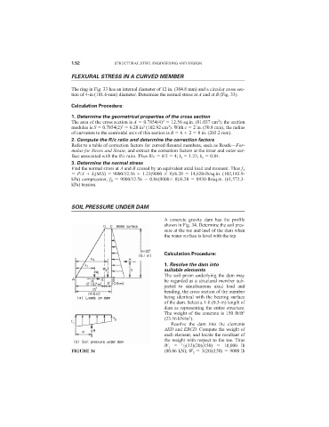
                                                              A concrete gravity dam has the profile
                                                              shown in Fig. 34. Determine the soil pres-
                                                              sure at the toe and heel of the dam when
                                                              the water surface is level with the top.


                                                              Calculation Procedure:

                                                              1. Resolve the dam into
                                                              suitable elements
                                                              The soil prism underlying the dam may
                                                              be regarded as a structural member sub-
                                                              jected to simultaneous axial load and
                                                              bending, the cross section of the member
                                                              being identical with the bearing surface
                                                              of the dam. Select a 1-ft (0.3-m) length of
                                                              dam as representing the entire structure.
                                                              The weight of the concrete is 150 lb/ft 3
                                                                       3
                                                              (23.56 kN/m ).
                                                                Resolve the dam into the elements
                                                              AED and EBCD. Compute the weight of
                                                              each element, and locate the resultant of
                                                              the weight with respect to the toe. Thus
                                                              W 1    1 /2(12)(20)(150)    18,000 lb
                            FIGURE 34                         (80.06 kN); W 2   3(20)(150)   9000 lb
   64   65   66   67   68   69   70   71   72   73   74