
Page 74 - Handbook of Civil Engineering Calculations, Second Edition
P. 74
STATICS, STRESS AND STRAIN, AND FLEXURAL ANALYSIS 1.57
respectively, to the slope and deflection y
at the corresponding section of the given
beam.
Assign supports to the conjugate beam
that are compatible with the end conditions
of the given beam. At A, the given beam has
a specific slope but zero deflection. Corre-
spondingly, the conjugate beam has a specif-
ic shear but zero moment; i.e., it is simply
supported at A.
At C, the given beam has a specific slope
and a specific deflection. Correspondingly,
the conjugate beam has both a shear and a
bending moment; i.e., it has a fixed support
at C.
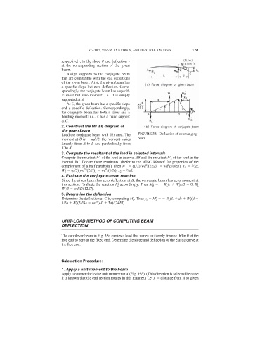
2. Construct the M/(EI) diagram of
the given beam
Load the conjugate beam with this area. The FIGURE 38. Deflection of overhanging
2
moment at B is wd /2; the moment varies beam.
linearly from A to B and parabolically from
C to B.
3. Compute the resultant of the load in selected intervals
Compute the resultant W
1 of the load in interval AB and the resultant W
2 of the load in the
interval BC. Locate these resultants. (Refer to the AISC Manual for properties of the
2
2
2
complement of a half parabola.) Then W
1 (L/2)[wd /(2EI)] wd L/(4EI); x 1 /3L;
2
3
3
W
2 (d/3)[wd /(2EI)] wd /(6EI); x 2 /4d.
4. Evaluate the conjugate-beam reaction
Since the given beam has zero deflection at B, the conjugate beam has zero moment at
this section. Evaluate the reaction R
L accordingly. Thus M
B R
L L W
1 L/3 0; R
L
2
W
1 /3 wd L/(12EI).
5. Determine the deflection
Determine the deflection at C by computing M
c . Thus y c M
c R
L (L d) W
1 (d
3
L/3) W
2 (3d/4) wd (4L 3d)/(24EI).
UNIT-LOAD METHOD OF COMPUTING BEAM
DEFLECTION
The cantilever beam in Fig. 39a carries a load that varies uniformly from w lb/lin ft at the
free end to zero at the fixed end. Determine the slope and deflection of the elastic curve at
the free end.
Calculation Procedure:
1. Apply a unit moment to the beam
Apply a counterclockwise unit moment at A (Fig. 39b). (This direction is selected because
it is known that the end section rotates in this manner.) Let x distance from A to given