Page 75 - Handbook of Civil Engineering Calculations, Second Edition
P. 75

1.58            STRUCTURAL STEEL ENGINEERING AND DESIGN
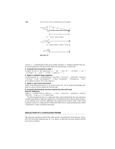


                                            FIGURE 39


                            section; w x   load intensity at the given section; M and m   bending moment at the giv-
                            en section induced by the actual load and by the unit moment, respectively.
                            2. Evaluate the moments in step 1
                                                                               2
                            Evaluate  M and  m. By proportion,  w x   w(L    x)/L;  M   (x /6)(2w    w x )
                                2
                                                    2
                             (wx /6)[2   (L   x)/L]   wx (3L   x)/(6L); m   1.
                            3. Apply a suitable slope equation
                                             L
                                                                   L
                                                                       2
                            Use the equation 	 A     0 [Mm/(EI)] dx. Then EI	 A     0 [wx 3L   x)/(6L)] dx   [w/(6L)]
                                   2
                                      3
                              L
                                                                                           3
                                                          4
                                                             L
                                                     3
                                                                            4
                                                                        4
                                                                                       1
                                0 (3Lx   x ) dx   [w/(6L)](3Lx /3   x /4)] 0   [w/(6L)](L   L /4); thus, 	 A   /8wL /
                            (EI) counterclockwise. This is the slope at A.
                            4. Apply a unit load to the beam
                            Apply a unit downward load at A as shown in Fig. 39c. Let m
 denote the bending mo-
                            ment at a given section induced by the unit load.
                            5. Evaluate the bending moment induced by the unit load;
                            find the deflection
                                                                   L
                                     L
                                                                       3
                            Apply y A     0 [Mm
/(EI)] dx. Then m
  x; EIy A     0 [wx (3L   x)/(6L)] dx   [w/(6L)]
                              L
                                                      4
                                3
                               0 x (3L   x) dx; y A   (11/120)wL /(EI).
                              The first equation in step 3 is a statement of the work performed by the unit moment at
                            A as the beam deflects under the applied load. The left-hand side of this equation express-
                            es the external work, and the right-hand side expresses the internal work. These work
                            equations constitute a simple proof of Maxwell’s theorem of reciprocal deflections, which
                            is presented in a later calculation procedure.
                            DEFLECTION OF A CANTILEVER FRAME
                            The prismatic rigid frame ABCD (Fig. 40a) carries a vertical load P at the free end. Deter-
                            mine the horizontal displacement of A by means of both the unit-load method and the
                            moment-area method.
   70   71   72   73   74   75   76   77   78   79   80