
Page 103 - Handbook of Electrical Engineering
P. 103
84 HANDBOOK OF ELECTRICAL ENGINEERING
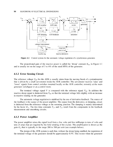
Figure 4.1 Control system for the automatic voltage regulation of a synchronous generator.
The proportional gain of the reactive power is called the ‘droop’ constant K da in Figure 4.1
and is usually set on the range of 3 to 6% of the rated MVA of the generator.
4.1.2 Error Sensing Circuit
The reference voltage V ref for the AVR is usually taken from the moving brush of a potentiometer
that is driven by a small servomotor inside the AVR controller. The servomotor receives ‘raise’ and
‘lower’ signals from control switches mounted locally on the AVR controller, remotely at the main
generator switchgear or at a control room.
The terminal voltage signal V is compared with the reference signal V ref . In addition the
reactive droop signal is deducted from V ref so that the terminal voltage falls slightly with an increase
in reactive loading on the generator.
The automatic voltage regulation is stabilised by the use of derivative feedback. The source of
the feedback is the output of the power amplifier. The output from the derivative, or damping, circuit
is deducted from the reference voltage at the summing junction. The damping is mainly determined
by the factor K f . The two time constants T f 1 and T f 2 result from the components in the feedback
measurement and smoothing circuits.
4.1.3 Power Amplifier
The power amplifier raises the signal level from a few volts and few milliamps to tens of volts and
tens of amps that are required by the field winding of the exciter. The amplification is shown as the
gain G a that is typically in the range 200 to 500 per unit (see example below).
The design of the AVR system is such that, without the droop being enabled, the regulation of
the terminal voltage of the generator should be approximately 0.5%. This occurs when the generator