
Page 106 - Handbook of Electrical Engineering
P. 106
AUTOMATIC VOLTAGE REGULATION 87
Equate the bracketed terms in (4.5) and (4.6)
V ref
G g − G g = V ref − 1.0
V 1
Hence,
(G g − 1.0)V 1
V ref = (4.7)
G g − V 1
Inserting the data gives V ref = 1.002897 pu
Substitute V ref into (4.6) to find G a ,
G g − V 1
G a = (4.8)
G g (V 1 − 1.0)
Inserting the data gives G a = 345.205 pu, which is of the correct order for an AVR.
The solution to the example can be found by using equations (4.1), (4.2) and (4.8) V ref can be
found from (4.7).
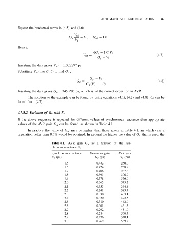
4.1.3.2 Variation of G a with X s
If the above sequence is repeated for different values of synchronous reactance then appropriate
values of the AVR gain G a can be found, as shown in Table 4.1.
In practice the value of G a may be higher than those given in Table 4.1, in which case a
regulation better than 0.5% would be obtained. In general the higher the value of G a that is used, the
Table 4.1. AVR gain G a as a function of the syn-
chronous reactance X s
Synchronous reactance Generator gain AVR gain
X s (pu) G g (pu) G a (pu)
1.5 0.442 250.0
1.6 0.424 268.9
1.7 0.408 287.8
1.8 0.393 306.9
1.9 0.378 326.0
2.0 0.365 345.2
2.1 0.353 364.4
2.2 0.341 383.7
2.3 0.330 403.1
2.4 0.320 422.5
2.5 0.310 442.0
2.6 0.301 461.5
2.7 0.292 481.0
2.8 0.284 500.5
2.9 0.276 520.1
3.0 0.269 539.7