
Page 112 - Handbook of Electrical Engineering
P. 112
AUTOMATIC VOLTAGE REGULATION 93
4.2.3 Determining of Saturation Constants
Saturation data for exciters and main generators can be described in an approximate manner by an
exponential function of the form,
S = Ae BVf d
In order to find A and B it is necessary to be given two values of S. In practice these two
values are usually called S E75 and S E100 , which will be discussed at the conclusion of this subsection.
The following procedure is applicable to both exciters and main generators and shows how any two
values of S can be used, and why S E75 and S E100 are preferred.
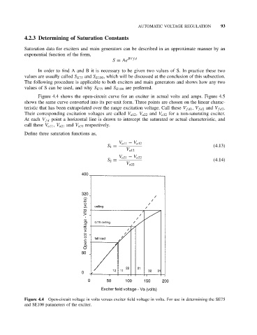
Figure 4.4 shows the open-circuit curve for an exciter in actual volts and amps. Figure 4.5
shows the same curve converted into its per-unit form. Three points are chosen on the linear charac-
teristic that has been extrapolated over the range excitation voltage. Call these V fd1 , V fd2 and V fd3 .
Their corresponding excitation voltages are called V a12 , V a22 and V a32 for a non-saturating exciter.
At each V fd point a horizontal line is drawn to intercept the saturated or actual characteristic, and
call these V a11 , V a21 and V a31 respectively.
Define three saturation functions as,
V a11 − V a12
S 1 = (4.13)
V a12
V a21 − V a22
S 2 = (4.14)
V a22
Figure 4.4 Open-circuit voltage in volts versus exciter field voltage in volts. For use in determining the SE75
and SE100 parameters of the exciter.