
Page 170 - Handbook of Electrical Engineering
P. 170
SWITCHGEAR AND MOTOR CONTROL CENTRES 153
Let,
−t
1 1 1
y lhs = − exp T d + (7.4)
X
d X d X d
and
−t
1
y rhs = exp Ta (7.5)
X
d
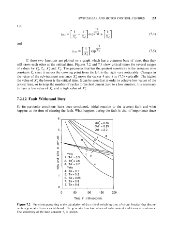
If these two functions are plotted on a graph which has a common base of time, then they
will cross each other at the critical time. Figures 7.2 and 7.3 show critical times for several ranges
of values for T , T a , X and X . The parameter that has the greatest sensitivity is the armature time
d d d
constants T a since it moves the crossing point from the left to the right very noticeably. Changes in
the value of the sub-transient reactance X move the curves 4 and 8 in (7.5) vertically. The higher
d
the value of X the lower is the critical time. It can be seen that in order to achieve low values of the
d
critical time, or to keep the number of cycles to the first current zero to a low number, it is necessary
to have a low value of T a and a high value of X .
d
7.2.12 Fault Withstand Duty
So far particular conditions have been considered, initial reaction to the severest fault and what
happens at the time of clearing the fault. What happens during the fault is also of importance since
Figure 7.2 Functions pertaining to the calculation of the critical switching time of circuit breaker that discon-
nects a generator from a switchboard. The generator has low values of sub-transient and transient reactances.
The sensitivity of the time constant T a is shown.