
Page 175 - Handbook of Electrical Engineering
P. 175
158 HANDBOOK OF ELECTRICAL ENGINEERING
second method is popular and uses a ‘synchronising check’ relay (25) to sense the voltage on
both sides of a circuit breaker. For the above mentioned dual incomer switchboard all three circuit
breakers would be equipped with the synchronising check relays.
7.6 CONTROL AND INDICATION DEVICES
The requirements for control and indication vary considerably depending upon the type of circuit,
e.g. incoming, busbar section or outgoing circuit, whether the equipment is a switchboard or a motor
control centre, high or low voltage, process duty, the need for remote indication and control, and
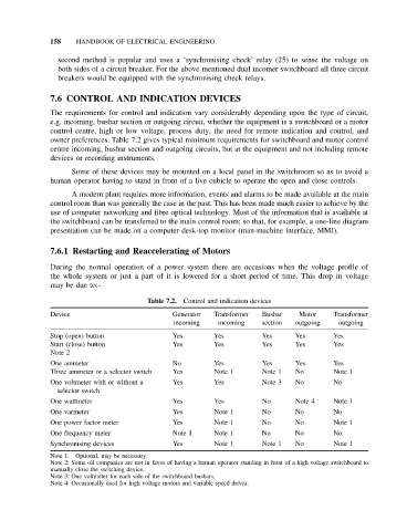
owner preferences. Table 7.2 gives typical minimum requirements for switchboard and motor control
centre incoming, busbar section and outgoing circuits, but at the equipment and not including remote
devices or recording instruments.
Some of these devices may be mounted on a local panel in the switchroom so as to avoid a
human operator having to stand in front of a live cubicle to operate the open and close controls.
A modern plant requires more information, events and alarms to be made available at the main
control room than was generally the case in the past. This has been made much easier to achieve by the
use of computer networking and fibre optical technology. Most of the information that is available at
the switchboard can be transferred to the main control room; so that, for example, a one-line diagram
presentation can be made on a computer desk-top monitor (man-machine interface, MMI).
7.6.1 Restarting and Reaccelerating of Motors
During the normal operation of a power system there are occasions when the voltage profile of
the whole system or just a part of it is lowered for a short period of time. This drop in voltage
may be due to:-
Table 7.2. Control and indication devices
Device Generator Transformer Busbar Motor Transformer
incoming incoming section outgoing outgoing
Stop (open) button Yes Yes Yes Yes Yes
Start (close) button Yes Yes Yes Yes Yes
Note 2
One ammeter No Yes Yes Yes Yes
Three ammeter or a selector switch Yes Note 1 Note 1 No Note 1
One voltmeter with or without a Yes Yes Note 3 No No
selector switch
One wattmeter Yes Yes No Note 4 Note 1
One varmeter Yes Note 1 No No No
One power factor meter Yes Note 1 No No Note 1
One frequency meter Note 1 Note 1 No No No
Synchronising devices Yes Note 1 Note 1 No Note 1
Note 1: Optional, may be necessary.
Note 2: Some oil companies are not in favor of having a human operator standing in front of a high voltage switchboard to
manually close the switching device.
Note 3: One voltmeter for each side of the switchboard busbars.
Note 4: Occasionally used for high voltage motors and variable speed drives.