
Page 177 - Handbook of Electrical Engineering
P. 177
160 HANDBOOK OF ELECTRICAL ENGINEERING
are also capable of carrying out relatively simple calculations such as active power, reactive power
and power factor of the circuit, number of attempted starts for a motor.
Transmission of information between switchboards and to other locations such as a control
room can be achieved by either optical fibre or ‘hard wire’ cables. Suitable interfaces are placed at
each end of the cables. As with many aspects of computing the speed of data transmission, method
of porting, the protocols available, memory capacity and speed of calculation are upgraded, improved
and superseded almost on a yearly basis. It is therefore necessary to be well aware of ‘the state of
the art’ in these subjects so that a system that is about to be superseded is not purchased.
The following description of integrated motor control systems (IMCS) is based upon Ref-
erence 7, for which permission to use the material therein was kindly given by Switchgear and
Instrumentation Ltd. The principles described can be used for low and high voltage switchgear that
contain plain feeders, interconnectors, incomers and busbar section circuit breakers, in addition to
motor feeders.
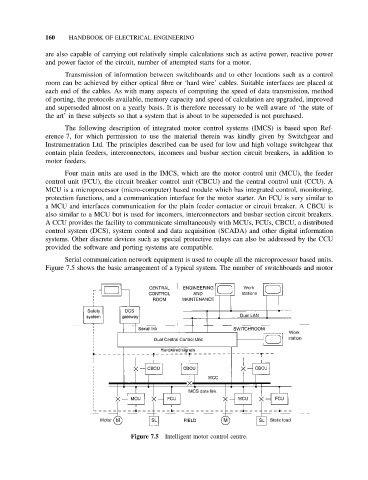
Four main units are used in the IMCS, which are the motor control unit (MCU), the feeder
control unit (FCU), the circuit breaker control unit (CBCU) and the central control unit (CCU). A
MCU is a microprocessor (micro-computer) based module which has integrated control, monitoring,
protection functions, and a communication interface for the motor starter. An FCU is very similar to
a MCU and interfaces communication for the plain feeder contactor or circuit breaker. A CBCU is
also similar to a MCU but is used for incomers, interconnectors and busbar section circuit breakers.
A CCU provides the facility to communicate simultaneously with MCUs, FCUs, CBCU, a distributed
control system (DCS), system control and data acquisition (SCADA) and other digital information
systems. Other discrete devices such as special protective relays can also be addressed by the CCU
provided the software and porting systems are compatible.
Serial communication network equipment is used to couple all the microprocessor based units.
Figure 7.5 shows the basic arrangement of a typical system. The number of switchboards and motor
Figure 7.5 Intelligent motor control centre.