
Page 209 - Handbook of Electrical Engineering
P. 209
CABLES, WIRES AND CABLE INSTALLATION PRACTICES 193
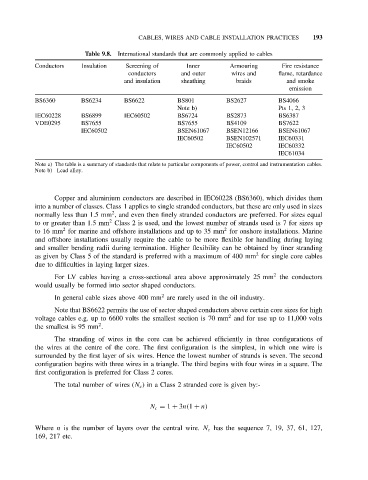
Table 9.8. International standards that are commonly applied to cables
Conductors Insulation Screening of Inner Armouring Fire resistance
conductors and outer wires and flame, retardance
and insulation sheathing braids and smoke
emission
BS6360 BS6234 BS6622 BS801 BS2627 BS4066
Note b) Pts 1, 2, 3
IEC60228 BS6899 IEC60502 BS6724 BS2873 BS6387
VDE0295 BS7655 BS7655 BS4109 BS7622
IEC60502 BSEN61067 BSEN12166 BSEN61067
IEC60502 BSEN102571 IEC60331
IEC60502 IEC60332
IEC61034
Note a) The table is a summary of standards that relate to particular components of power, control and instrumentation cables.
Note b) Lead alloy.
Copper and aluminium conductors are described in IEC60228 (BS6360), which divides them
into a number of classes. Class 1 applies to single stranded conductors, but these are only used in sizes
2
normally less than 1.5 mm , and even then finely stranded conductors are preferred. For sizes equal
2
to or greater than 1.5 mm Class 2 is used, and the lowest number of strands used is 7 for sizes up
2
2
to 16 mm for marine and offshore installations and up to 35 mm for onshore installations. Marine
and offshore installations usually require the cable to be more flexible for handling during laying
and smaller bending radii during termination. Higher flexibility can be obtained by finer stranding
2
as given by Class 5 of the standard is preferred with a maximum of 400 mm for single core cables
due to difficulties in laying larger sizes.
2
For LV cables having a cross-sectional area above approximately 25 mm the conductors
would usually be formed into sector shaped conductors.
2
In general cable sizes above 400 mm are rarely used in the oil industry.
Note that BS6622 permits the use of sector shaped conductors above certain core sizes for high
2
voltage cables e.g. up to 6600 volts the smallest section is 70 mm and for use up to 11,000 volts
2
the smallest is 95 mm .
The stranding of wires in the core can be achieved efficiently in three configurations of
the wires at the centre of the core. The first configuration is the simplest, in which one wire is
surrounded by the first layer of six wires. Hence the lowest number of strands is seven. The second
configuration begins with three wires in a triangle. The third begins with four wires in a square. The
first configuration is preferred for Class 2 cores.
The total number of wires (N c ) in a Class 2 stranded core is given by:-
N c = 1 + 3n(1 + n)
Where n is the number of layers over the central wire. N c has the sequence 7, 19, 37, 61, 127,
169, 217 etc.