
Page 226 - Handbook of Electrical Engineering
P. 226
210 HANDBOOK OF ELECTRICAL ENGINEERING
Large or complete voltage depressions occur as a result of short circuits at or near the switch-
board. The duration of the voltage depression is mainly determined by the response time of the relay
or fuse protective devices closest to the point of fault. Individual oil companies tend to have their
own philosophy for detecting and responding to the voltage depressions, and to the reacceleration of
motors. In order to account for voltage depression and the reacceleration of large groups of motors it
may be necessary to allow up to 10% for the drop in busbar voltage during the whole reacceleration
period, which may be several seconds. At the same time the voltage received at the terminals of each
load should not fall below 80% of its nameplate value. This represents a serious constraint on the
sizing of motor feeder cables in particular, due to the high starting currents and their very low power
factors. The situation is made worse for long route lengths with low voltage high power motors e.g.,
400 volts, 90 to 200 kW motors. Unusually large conductor sizes will result in these situations, which
can also make their termination at the load end awkward.
The voltage drop in a cable is due to its series resistance and series inductive reactance. The
shunt capacitive reactance is usually too large to be considered for cables installed in a typical plant.
However, for long distance high voltage cables, such as submarine cables, the shunt capacitance may
need to be included in the calculations of voltage drop.
9.4.3.1 Volt drop in short cables
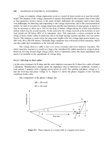
Let the series resistance be R ohms and the series inductive reactance be X ohms for a cable of length
l kilometre. Manufacturers usually quote the impedance data in ohms/km or mohms/m. Assume a
load current I amperes with a lagging power factor of cos Ø. The sending end phase voltage is V s
and the receiving end phase voltage is V r . Figure 9.1 shows the phasor diagram of the volt-drop
conditions in the cable.
The components of the phasor voltages are:-
AB = IR cos Ø
BE = IR sin Ø
Figure 9.1 Phasor diagram of a loaded cable at a lagging power factor.