
Page 225 - Handbook of Electrical Engineering
P. 225
CABLES, WIRES AND CABLE INSTALLATION PRACTICES 209
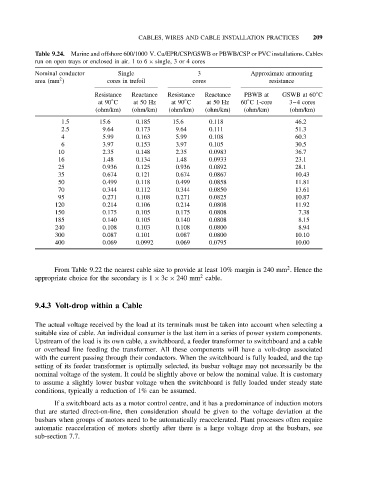
Table 9.24. Marine and offshore 600/1000 V. Cu/EPR/CSP/GSWB or PBWB/CSP or PVC installations. Cables
run on open trays or enclosed in air. 1 to 6 × single, 3 or 4 cores
Nominal conductor Single 3 Approximate armouring
2
area (mm ) cores in trefoil cores resistance
◦
Resistance Reactance Resistance Reactance PBWB at GSWB at 60 C
◦
◦
◦
at 90 C at 50 Hz at 90 C at 50 Hz 60 C1-core 3–4 cores
(ohm/km) (ohm/km) (ohm/km) (ohm/km) (ohm/km) (ohm/km)
1.5 15.6 0.185 15.6 0.118 46.2
2.5 9.64 0.173 9.64 0.111 51.3
4 5.99 0.163 5.99 0.108 60.3
6 3.97 0.153 3.97 0.105 30.5
10 2.35 0.148 2.35 0.0983 36.7
16 1.48 0.134 1.48 0.0933 23.1
25 0.936 0.125 0.936 0.0892 28.1
35 0.674 0.121 0.674 0.0867 10.43
50 0.499 0.118 0.499 0.0858 11.81
70 0.344 0.112 0.344 0.0850 13.61
95 0.271 0.108 0.271 0.0825 10.87
120 0.214 0.106 0.214 0.0808 11.92
150 0.175 0.105 0.175 0.0808 7.38
185 0.140 0.105 0.140 0.0808 8.15
240 0.108 0.103 0.108 0.0800 8.94
300 0.087 0.101 0.087 0.0800 10.10
400 0.069 0.0992 0.069 0.0795 10.00
2
From Table 9.22 the nearest cable size to provide at least 10% margin is 240 mm . Hence the
2
appropriate choice for the secondary is 1 × 3c × 240 mm cable.
9.4.3 Volt-drop within a Cable
The actual voltage received by the load at its terminals must be taken into account when selecting a
suitable size of cable. An individual consumer is the last item in a series of power system components.
Upstream of the load is its own cable, a switchboard, a feeder transformer to switchboard and a cable
or overhead line feeding the transformer. All these components will have a volt-drop associated
with the current passing through their conductors. When the switchboard is fully loaded, and the tap
setting of its feeder transformer is optimally selected, its busbar voltage may not necessarily be the
nominal voltage of the system. It could be slightly above or below the nominal value. It is customary
to assume a slightly lower busbar voltage when the switchboard is fully loaded under steady state
conditions, typically a reduction of 1% can be assumed.
If a switchboard acts as a motor control centre, and it has a predominance of induction motors
that are started direct-on-line, then consideration should be given to the voltage deviation at the
busbars when groups of motors need to be automatically reaccelerated. Plant processes often require
automatic reacceleration of motors shortly after there is a large voltage drop at the busbars, see
sub-section 7.7.