
Page 236 - Handbook of Electrical Engineering
P. 236
220 HANDBOOK OF ELECTRICAL ENGINEERING
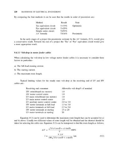
By comparing the four methods it can be seen that the results in order of pessimism are:-
Method Result Note
Tee equivalent circuit 5.419% Optimistic
Pye equivalent circuit 5.429%
Simple series circuit 5.653%
V formula 5.816% Pessimistic
In the early stages of a project the pessimistic estimate by the V formula, (9.3), would give
a conservative result. Towards the end of a project the ‘Tee’ or ‘Pye’ equivalent circuit would give
a more appropriate result.
9.4.3.3 Volt-drop in motor feeder cables
When calculating the volt-drop in low voltage motor feeder cables it is necessary to consider three
factors in particular:-
a) The full-load running current.
b) The starting current.
c) The maximum route length.
Typical limiting values for the steady state volt-drop at the receiving end of LV and HV
cables are:-
Receiving end consumer Allowable volt-drop% of nominal
HV switchboard (no motors) 1.0
HV motor control centre 1.0
LV main switchboard (no motors) 1.0
LV main motor control centre 1.0
LV auxiliary motor control centre 2.0 to 3.0
HV motor terminals at full-load 1.5 to 3.0
LV motor terminals at full-load 2.5 to 5.0
HV motor terminals at starting 15 to 20
LV motor terminals at starting 20
Equation (9.3) can be used to determine the maximum route length that can be accepted for a)
and b) above. Usually two different values of route length will be obtained and the shortest should be
taken for selecting the cable size. Equation (9.3) can be transposed to find the route length as follows,
√
3I(rl cos Ø + xl sin Ø)
V = 100%
V
V. V
l = √ km (9.5)
100 3I(r cos Ø + x sin Ø)