
Page 241 - Handbook of Electrical Engineering
P. 241
CABLES, WIRES AND CABLE INSTALLATION PRACTICES 225
currents. The starting, or run-up, time durations for low voltage motors are usually in the order of a
few seconds whereas for high voltage motors the duration can be up to 15 seconds when pumps and
compressors are being started.
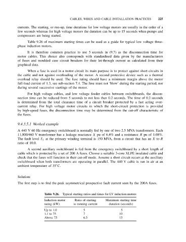
Table 9.26 of maximum starting times can be used as a guide for typical low voltage three-
phase induction motors.
It is therefore common practice to use 5 seconds in (9.7) as the disconnection time for
motor cables. This choice also corresponds with standardised data given by the manufacturers
of fuses and moulded case circuit breakers for their let-through current as calculated from their
graphical data.
When a fuse is used in a motor circuit its main purpose is to protect against short circuits in
the cable and not against overloading of the motor. A second protective device such as a thermal
overload relay should be used. The fuse rating should have a minimum margin above the motor
full-load current of 1.3, see sub-section 7.4. The fuse must not ‘blow’ during the starting period, nor
during several successive startings of the motor.
For high voltage cables, and low voltage feeder cables between switchboards, the discon-
nection time can be reduced from 5 seconds to not less than 0.2 seconds. The time of 0.2 seconds
is determined from the total clearance time of a circuit breaker protected by a fast acting over-
current relay. For high voltage motor circuits in which the short-circuit protection is provided
by high-speed fuses, the disconnection time may be determined from the cut-off characteristic of
the fuses.
9.4.3.5.1 Worked example
A 440 V 60 Hz emergency switchboard is normally fed by one of two 2.5 MVA transformers. Each
11,000/460 V transformer has a leakage reactance X pu of 6.4% and a resistance R pu of 1.08%.
The fault level S f at the primary winding terminal is 150 MVA, from a circuit that has an X-to-R
ratio of 10.0.
A second auxiliary switchboard is fed from the emergency switchboard by a short length of
cable which is protected by a set of 200 A fuses. Choose a suitable 3-core XLPE insulated cable and
check that the fuses will function in their cut-off mode. Assume a short circuit occurs at the auxiliary
switchboard when both transformers are operating in parallel. The 440 V cable is run in air at an
◦
ambient temperature of 35 C.
Solution:
The first step is to find the peak asymmetrical prospective fault current seen by the 200A fuses.
Table 9.26. Typical starting ratios and times for LV induction motors
Induction motor Ratio of starting Maximum starting time
rating (kW) to running current duration (seconds)
Up to 1.0 5 5
1.1to75 7 10
Above 75 6.5 15