
Page 289 - Handbook of Electrical Engineering
P. 289
FAULT CALCULATIONS AND STABILITY STUDIES 275
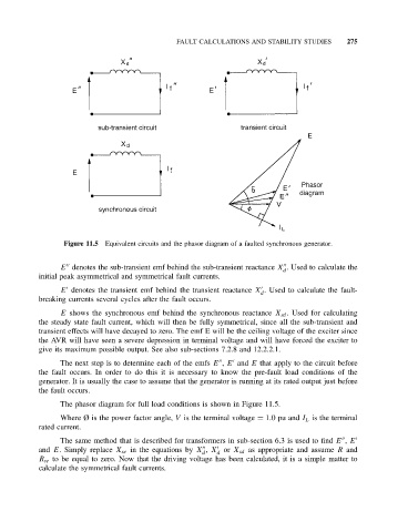
Figure 11.5 Equivalent circuits and the phasor diagram of a faulted synchronous generator.
E denotes the sub-transient emf behind the sub-transient reactance X . Used to calculate the
d
initial peak asymmetrical and symmetrical fault currents.
E denotes the transient emf behind the transient reactance X . Used to calculate the fault-
d
breaking currents several cycles after the fault occurs.
E shows the synchronous emf behind the synchronous reactance X sd . Used for calculating
the steady state fault current, which will then be fully symmetrical, since all the sub-transient and
transient effects will have decayed to zero. The emf E will be the ceiling voltage of the exciter since
the AVR will have seen a severe depression in terminal voltage and will have forced the exciter to
give its maximum possible output. See also sub-sections 7.2.8 and 12.2.2.1.
The next step is to determine each of the emfs E , E and E that apply to the circuit before
the fault occurs. In order to do this it is necessary to know the pre-fault load conditions of the
generator. It is usually the case to assume that the generator is running at its rated output just before
the fault occurs.
The phasor diagram for full load conditions is shown in Figure 11.5.
Where Ø is the power factor angle, V is the terminal voltage = 1.0pu and I L is the terminal
rated current.
The same method that is described for transformers in sub-section 6.3 is used to find E , E
and E. Simply replace X se in the equations by X , X or X sd as appropriate and assume R and
d d
R se to be equal to zero. Now that the driving voltage has been calculated, it is a simple matter to
calculate the symmetrical fault currents.