
Page 311 - Handbook of Electrical Engineering
P. 311
FAULT CALCULATIONS AND STABILITY STUDIES 297
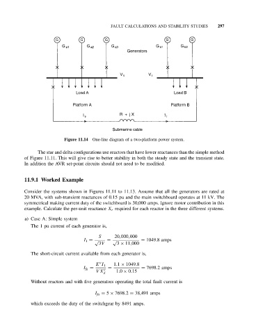
Figure 11.14 One-line diagram of a two-platform power system.
The star and delta configurations use reactors that have lower reactances than the simple method
of Figure 11.11. This will give rise to better stability in both the steady state and the transient state.
In addition the AVR set-point circuits should not need to be modified.
11.9.1 Worked Example
Consider the systems shown in Figures 11.11 to 11.13. Assume that all the generators are rated at
20 MVA, with sub-transient reactances of 0.15 pu and the main switchboard operates at 11 kV. The
symmetrical making current duty of the switchboard is 30,000 amps. Ignore motor contribution in this
example. Calculate the per-unit reactance X r required for each reactor in the three different systems.
a) Case A: Simple system
The 1 pu current of each generator is,
S 20,000,000
I 1 = √ = √ = 1049.8 amps
3V 3 × 11,000
The short-circuit current available from each generator is,
E I 1 1.1 × 1049.8
I fg = = = 7698.2 amps
VX 1.0 × 0.15
d
Without reactors and with five generators operating the total fault current is
I fa = 5 × 7698.2 = 38,491 amps
which exceeds the duty of the switchgear by 8491 amps.