
Page 325 - Handbook of Electrical Engineering
P. 325
312 HANDBOOK OF ELECTRICAL ENGINEERING
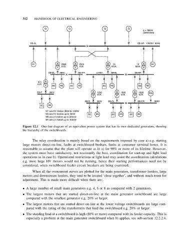
Figure 12.1 One-line diagram of an equivalent power system that has its own dedicated generators, showing
the hierarchy of the switchboards.
The relay coordination is mainly based on the requirements imposed by case a) e.g. starting
large motors direct-on-line, faults at switchboard busbars, faults at consumer terminal boxes. It is
reasonable to assume that the plant will operate as in a) for 90% or more of its lifetime. However,
the system must have satisfactory, not necessarily the best, coordination for start-up and light load
operations as in case b). Operational restrictions at light load may assist the coordination calculations
e.g. most large HV motors would not be running, hence their starting performances need not be
considered, when switchboard feeder circuit breakers are being examined.
When all the overcurrent curves are plotted for the main generators, transformer feeders, large
motors and downstream feeders, they tend to be located ‘close together’, and without much room for
adjustment. This is made more difficult when there are:-
• A large number of small main generators e.g. 4, 6 or 8 as compared with 2 generators.
• The largest motors that are started direct-on-line at the main generator switchboard are large
compared with the smallest generator e.g. 20% or larger.
• The largest motors that are started direct-on-line at the lower voltage switchboards are large com-
pared with the rating of the transformers that feed the switchboard e.g. 20% or larger.
• The standing load at a switchboard is high (80% or more) compared with its feeder capacity. This is
especially a problem at the main generator switchboard when b) applies, see sub-section 12.2.2.4.