
Page 328 - Handbook of Electrical Engineering
P. 328
PROTECTIVE RELAY COORDINATION 315
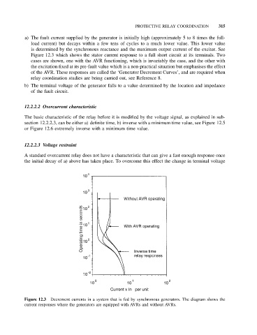
a) The fault current supplied by the generator is initially high (approximately 5 to 8 times the full-
load current) but decays within a few tens of cycles to a much lower value. This lower value
is determined by the synchronous reactance and the maximum output current of the exciter. See
Figure 12.3 which shows the stator current response to a full short circuit at its terminals. Two
cases are shown, one with the AVR functioning, which is invariably the case, and the other with
the excitation fixed at its pre-fault value which is a non-practical situation but emphasises the effect
of the AVR. These responses are called the ‘Generator Decrement Curves’, and are required when
relay coordination studies are being carried out, see Reference 8.
b) The terminal voltage of the generator falls to a value determined by the location and impedance
of the fault circuit.
12.2.2.2 Overcurrent characteristic
The basic characteristic of the relay before it is modified by the voltage signal, as explained in sub-
section 12.2.2.3, can be either a) definite time, b) inverse with a minimum time value, see Figure 12.5
or Figure 12.6 extremely inverse with a minimum time value.
12.2.2.3 Voltage restraint
A standard overcurrent relay does not have a characteristic that can give a fast enough response once
the initial decay of a) above has taken place. To overcome this effect the change in terminal voltage
Figure 12.3 Decrement currents in a system that is fed by synchronous generators. The diagram shows the
current responses where the generators are equipped with AVRs and without AVRs.