
Page 333 - Handbook of Electrical Engineering
P. 333
320 HANDBOOK OF ELECTRICAL ENGINEERING
Since the power from the prime-mover cannot be transmitted from the generator there will be a
surplus of mechanical power which will accelerate the rotor to a speed greater than the synchronous
speed. Since there is also no excitation the only possible conversion of power will be a small
contribution due to saliency. The generator will tend to be seen from the power system as a shunt
reactor that has a varying X-to-R ratio. Therefore the generator can be shown on an impedance
diagram as occupying a region of negative reactance with excursion into both the positive and
negative resistance quadrants. If the condition were to be allowed to persist until steady fluctuations
became established, then the shape appearing in the impedance diagram would follow a steady locus
in the lower two quadrants of the diagram. Consequently a part of this region can be chosen as the
response characteristic of a ‘loss-of-excitation’ relay. A circle is chosen as a suitable shape within
the region.
When the field is lost the movement into the critical leading power factor and high rotor
current regions takes a finite time, which depends upon the pre-disturbance power being generated
and the moment of inertia of the generator and its prime-mover. Consequently the stator current
phase angle and power factor can be monitored by a relay located in the stator current circuit, and
be set to trip the generator when a critical point is reached.
A field failure relay (40) is usually an ‘admittance’ relay with an offset admittance zone. The
tripping zone is usually determined from a circle. The relay receives a current signal and a voltage
signal from the stator terminals. The ‘impedance’ circle of the generator is determined and located
by the following features.
A circle is located in an x-y plane where the x-axis is −R to the left and +R to the right.
The y-axis is +X vertically above the x-axis and −X below. The circle is centred in x-y coordinates
as + R(−(0.5to0.75)X − (0.5to 1.0))X d where R can be zero or a small positive value. The
d
diameter of the circle is chosen between 0.5 to 1.0 times X d . All points on the circle must lie in the
negative y-axis region. The construction of the circular characteristic of the relay is also described
in References 1, 3 and 4.
The reactance settings are converted into admittances by inversion and then used as settings for
the relay. The relay setting ranges will usually exceed the requirements of the generator impedance
circle. A time delay range of 0.5 to 10 seconds is usually adequate for the protection tripping setting,
3 or 4 seconds would be typical settings.
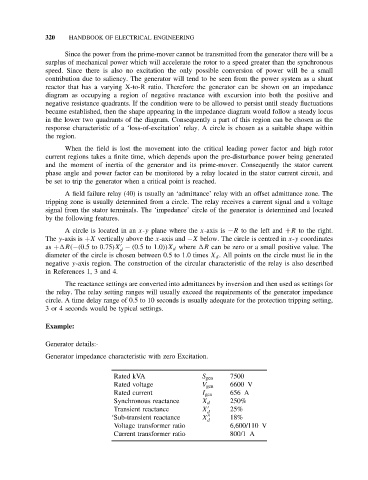
Example:
Generator details:-
Generator impedance characteristic with zero Excitation.
Rated kVA S gen 7500
Rated voltage V gen 6600 V
Rated current I gen 656 A
Synchronous reactance X d 250%
Transient reactance X 25%
d
‘Sub-transient reactance X 18%
d
Voltage transformer ratio 6,600/110 V
Current transformer ratio 800/1 A