
Page 334 - Handbook of Electrical Engineering
P. 334
PROTECTIVE RELAY COORDINATION 321
Conversion factor for referring the generator reactances to the CT and VT secondary circuits:-
2
X gen % × V gen × CT ratio
X sec =
100 × S gen × VT ratio
2
X gen % × 6600 × 800 × 110
=
100 × 750,0000 × 1 6600
X gen %
= × 5.808 × 13.333
100
X sec = X gen % × 0.7744 ohms
X = 25.0 × 0.7744 = 19.36 ohms
dsec
X dsec = 250.0 × 0.7744 = 193.6 ohms
Choose an offset of 0.75 X , a circle diameter of 0.5X d . This will allow the generator to run
d
in the leading power factor zone with a large transient rotor angle (up to 120 degrees).
Relay offset = 0.75 × 19.36 = 14.52 ohms
rounded to 15.0 ohms
Relay circle diameter = 0.5 × 193.6 = 96.8 ohms
rounded to 100.0 ohms
Relay time delay, choose 4 seconds.
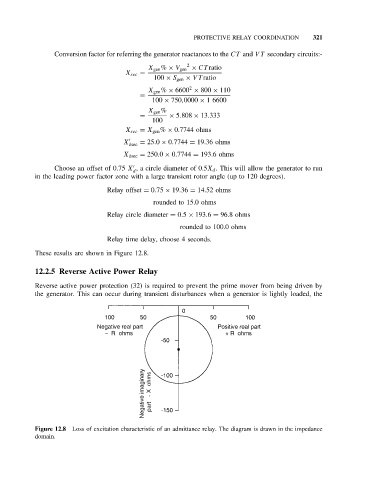
These results are shown in Figure 12.8.
12.2.5 Reverse Active Power Relay
Reverse active power protection (32) is required to prevent the prime mover from being driven by
the generator. This can occur during transient disturbances when a generator is lightly loaded, the
Figure 12.8 Loss of excitation characteristic of an admittance relay. The diagram is drawn in the impedance
domain.