
Page 378 - Handbook of Electrical Engineering
P. 378
366 HANDBOOK OF ELECTRICAL ENGINEERING
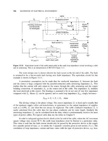
Figure 13.11 Equivalent circuit of the earth return paths in the earth loop impedance circuit involving a cable
and its armouring. This is an interpretation of BS7430 Clause 3.13.
The worst design case is shown wherein the fault occurs at the far end of the cable. The fault
is assumed to be a line-to-earth fault having zero fault impedance. The equivalent circuit for this
example is shown in Figure 13.11.
A pessimistic assumption can be made that the steelwork impedance Z e between the fault
and the source is large compared with the parallel-connected cable armouring impedance Z a .This
implies that the current will only return to the source through the cable armouring and the copper
bonding connection, of impedance Z b , at the source-end of the cable. The impedance Z b includes
the local steelwork at the source. The bonding is assumed to be in tact and of very low impedance
compared with Z a . Hence Z b can be ignored, and so earth loop impedance Z loop simply becomes:-
ohms
Z loop = Z s + Z c + Z a
The driving voltage is the phase voltage. The source impedance Z s is fixed and is usually that
of the upstream supply cables and transformers, or generators (or the output impedance of supplies
such as a UPS). Z s can often but not always be neglected. The cable conductor impedance Z c is
easily calculated from the cable data for one phase conductor and its route length. Similarly the
armouring impedance Z a can be calculated from the data, which is predominantly resistive for most
types of power cables. For typical cable data see the tables in Chapter 9.
In order to safeguard against electric shock at the far end of the cable, where the AC root mean
square voltage may exceed 50 V, the earth loop impedance must be limited to a particular value.
This value is such that the fault current should only be passed by the protective device at the supply
for a specific period of time, i.e. to satisfy the I-squared-t criterion given in sub-section 13.1.1. The
correlation of loop impedance, current and time varies with the type of protective device, e.g. fuse,