
Page 382 - Handbook of Electrical Engineering
P. 382
370 HANDBOOK OF ELECTRICAL ENGINEERING
per-unit or percentage factors that relate to the grid geometry. These are then used to scale down the
GPR by simple multiplication. The mesh voltage E m is usually more of a constraint on the design
than the step voltage E s . The IEEE80 standard provides graphs of E m and E s for different mesh
configurations, (Figures B1 to B5 therein).
In Reference 3 a typical design of a grid of large area would be to bury it to about 0.5 m and
choose each mesh in the grid to have sides of length about 5 or 6 m. This would give a good starting
point for a series of calculations.
13.3.5.4 Fault current entering the ground
For most practical designs the calculation of a ‘single line-to-ground or L-G’ fault current should be
adequate. Assume the fault occurs at the pole location and that the pole is at a long distance from
the source of power. Assume for a simple example that the overhead line is a simple radial circuit
fed only from one end, and that the line is furnished with an overhead earthing conductor. To be
conservative assume that the earthing conductor is only bonded to the pole in question and to the
neutral earthing point at the source end. The source is considered to be earthed through a neutral
earthing resistor (NER) having a resistance R n .
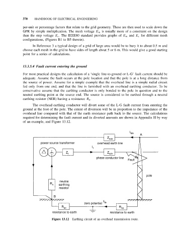
The overhead earthing conductor will divert some of the L-G fault current from entering the
ground at the foot of the pole. The extent of diversion will be in proportion to the impedance of the
overhead line compared with that of the earth resistance path back to the source. The calculations
required for determining the fault current and its diverted amounts are shown in Appendix H by way
of an example, and Figure 13.12.
Figure 13.12 Earthing circuit of an overhead transmission route.