
Page 392 - Handbook of Electrical Engineering
P. 392
380 HANDBOOK OF ELECTRICAL ENGINEERING
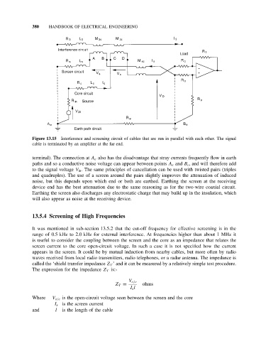
Figure 13.15 Interference and screening circuit of cables that are run in parallel with each other. The signal
cable is terminated by an amplifier at the far end.
terminal). The connection at A e also has the disadvantage that stray currents frequently flow in earth
paths and so a conductive noise voltage can appear between points A e and B e , and will therefore add
to the signal voltage V in . The same principles of cancellation can be used with twisted pairs (triples
and quadruples). The use of a screen around the pairs slightly improves the attenuation of induced
noise, but this depends upon which end or both are earthed. Earthing the screen at the receiving
device end has the best attenuation due to the same reasoning as for the two-wire coaxial circuit.
Earthing the screen also discharges any electrostatic charge that may build up in the insulation, which
will also appear as noise at the receiving device.
13.5.4 Screening of High Frequencies
It was mentioned in sub-section 13.5.2 that the cut-off frequency for effective screening is in the
range of 0.5 kHz to 2.0 kHz for external interference. At frequencies higher than about 1 MHz it
is useful to consider the coupling between the screen and the core as an impedance that relates the
screen current to the core open-circuit voltage. In such a case it is not specified how the current
appears in the screen. It could be by mutual induction from nearby cables, but more often by radio
waves received from local radio transmitters, radio telephones, or a radar antenna. The impedance is
called the ‘shield transfer impedance Z T ’ and it can be measured by a relatively simple test procedure.
The expression for the impedance Z T is:-
V o/c
Z T = ohms
I s l
Where V o/c is the open-circuit voltage seen between the screen and the core
I s is the screen current
and l is the length of the cable