
Page 393 - Handbook of Electrical Engineering
P. 393
EARTHING AND SCREENING 381
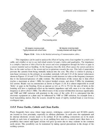
Figure 13.16 Holes in the braided armouring of instrumentation cables.
This impedance can be used to analyse the effect of laying cores close together in a multi-core
cable, and whether or not to use individual screens for pairs, triples and quadruples. The impedance
is a complex function of skin effect in the screen and wave propagation through the holes or gaps in
a screen material such as braiding. As the frequency rises the skin effect causes the screen current to
flow on the outer surface of the screen and not to penetrate towards the core. This lack of penetration
prevents the currents from being mutually induced into the core. The effect is similar to placing a
non-linear resistance in the primary or secondary terminals A-B and C-D of the mutual inductances
shown in Figures 13.14 and 13.15. This resistance would decrease in value as the frequency increases
due to the increased presence of eddy currents. The effectiveness of the screen due to skin effect
reaches a maximum at about 1 MHz for typical braided screens, and about 5 MHz for aluminium
foil screens. Braids vary in construction as shown in Figure 13.16. It is almost impossible to avoid
‘holes’ or gaps in the braiding. Even an amount as low as 2% to 5% for the area of holes in the
braiding will have a significant effect on the transfer impedance and will cause it to rise when the
frequency is above about 1 MHz. The effectiveness of the screen will therefore decrease significantly
and VHF and UHF radiation will penetrate to the cores of the cable. If it is anticipated that the
electronic equipment in a plant may be influenced by VHF or UHF radiation, for example from a
local transmitting station, then the screens should be made of tightly meshed braid or non-ferrous
overlapped tape.
13.5.5 Power Earths, Cubicle and Clean Earths
Plants frequently have areas where large motors, switchgear, control panels and SCADA panels
are located in close proximity, especially in offshore platforms. In such cases the equipment and
its internal electronic circuits needs to be earthed. If all the earthing connections are to be made
locally at each item of equipment, e.g. to an earthing boss next to a control panel, then there is a
possibility that control and signal circuits will pick up noise due to stray currents in the common
earth circuit. This possibility can be minimised by taking special precautions in the design of the
earthing systems.