
Page 52 - Handbook of Electrical Engineering
P. 52
GAS TURBINE DRIVEN GENERATORS 31
Where
1
d =
2δ
which when substituted in (2.26) gives the maximum work done U outemax .
2.2.2.1 Worked example
Find r pmax for the worked example in sub-section 2.2.1.1.
Given that,
◦
T 1 = 298 K, T 3 = 1223 C,
r = 1.4,η t = 0.86 and η c = 0.894
γ 1.4
d = = =−1.75
2(1 − γ) 2(1.0 − 1.4)
298
−1.75
r pmax =
1223(0.894)(0.86)
= 0.3169 −1.75 = 7.4
2.2.3 Variation of Specific Heat
As mentioned in sub-section 2.2 the specific heat C p changes with temperature. From Reference 4,
Figure 4.4, an approximate cubic equation can be used to describe C p in the range of temperature
300 K to 1300 K when the fuel-to-air ratio by mass is 0.01, and for the air alone for compression, as
shown in Table 2.1. The specific heat for the compressor can be denoted as C pc and for the turbine
C pt . The appropriate values of C pc and C pt can be found iteratively from the cubic expression and
equations (2.24) and (2.25). At each iteration the average of T 1 and T 2 can be used to recalculate C pc ,
and T 3 and T 4 to recalculate C pt . The initial value of γ can be taken as 1.4 in both cases, and C v
can be assumed constant at 0.24/1.4 = 0.171 kcal/kg K. The pressure ratio is constant. Having found
suitable values of C pc and C pt it is now possible to revise the equations for thermal efficiency η pa
and output energy U outea , where the suffix ‘a’ is added to note the inclusion of variations in specific
heat C p .
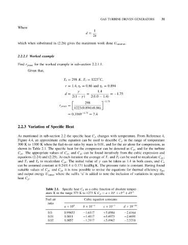
Table 2.1. Specific heat C p as a cubic function of absolute temper-
2
ature K in the range 373 K to 1273 K C p = a + bT + cT + dT 3
Fuel-air Cubic equation constants
ratio
a × 10 0 b × 10 −4 c × 10 −7 d × 10 −10
0.0 0.99653 −1.6117 +5.4984 −2.4164
0.01 1.0011 −1.4117 +5.4973 −2.4691
0.02 1.0057 −1.2117 +5.4962 −2.5218