Page 55 - Handbook of Electrical Engineering
P. 55

34    HANDBOOK OF ELECTRICAL ENGINEERING

              The turbine energy changes from U tea to U tea +  U tea . Substitute (2.40) into (2.29),

                                                            nt
                          U tea +  U tea = C pt T 3 (1 − (r pt +  r pt ) )η t
                                                               nt−1           nt
                                                       n   n t P 3        n t r pt
                                      = C pt T 3 η t 1 − r pt +    P 223 −       P 4
                                                               nt
                                                             P 4            P 4
              from which,

                                                    nt−1  r pt  P 4 − r pt  P 1 −  P 23
                                 U tea =+n t η t C pt T 3 r pt                               (2.41)
                                                                   P 4
              The change in efficiency η pa in (2.33) is,

                                                  U tea +  U tea − U cea −  U cea
                                     η pa +  η pa =                                          (2.42)
                                                        U fea +  U fea
              from which, by substituting for  U tea , U cea = 0.0and  U fea = 0.0 and deducting the initial con-
              ditions gives,
                                                          U tea
                                                   η pa =                                    (2.43)
                                                          U fea
              The change in work done on the generator

                                               U outea =  U tea kJ/kg                        (2.44)

              Note that in the above analysis the signs of the practical changes are,

                                                 P 1 is negative
                                                 P 23 is negative
              and                                P 4 is positive

                    The pressure drops  P 1 and  P 4 are dependent upon the layout of the gas turbine generator,
              the dimensions of the ducting systems and the specification of silencers and filters.  P 23 is fixed by the
              design of the combustion system and cannot be changed by external factors such as ducting systems.


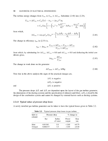
              2.2.4.1 Typical values of pressure drop losses

              A newly installed gas turbine generator can be taken to have the typical losses given in Table 2.2.

                                   Table 2.2.  Typical pressure drop losses in gas turbine
                                 Inlet or      Pressure drop        % change in
                                 exhaust
                                             Bar        Inches    Power     Heat
                                                       of water   output    rate
                                 Inlet     0.01245       5.0      −2.00    +0.75
                                 Exhaust   0.006227      2.5      −0.50    +0.40
   50   51   52   53   54   55   56   57   58   59   60