
Page 549 - Handbook of Electrical Engineering
P. 549
540 HANDBOOK OF ELECTRICAL ENGINEERING
machine recovers its shaft speed and system frequency. Note that some of the larger disturbances
would not normally occur in a practical power system, but are included to illustrate and compare the
operation of the control systems involved. The two-shaft machine exhibits a wider deviation in shaft
speed and system frequency than the single-shaft machine, and generally takes longer to recover. This
illustrates the customarily held view that a single-shaft machine has a more superior performance
than a two-shaft machine for electrical power applications.
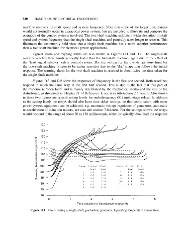
Typical alarm and tripping limits are also shown in Figures D.1 and D.4. The single-shaft
machine reaches these limits generally faster than the two-shaft machine, again due to the effect of
the ‘least signal selector’ safety control system. The trip setting for the over-temperature limit for
the two-shaft machine is seen to be rather sensitive due to the ‘flat’ shape that follows the initial
response. The warning alarm for the two-shaft machine is reached in about twice the time taken for
the single-shaft machine.
Figures D.3 and D.6 show the responses of frequency in the first one second. Both machines
respond in much the same way in the first half second. This is due to the fact that this part of
the response is ‘open loop’ and is mainly determined by the mechanical inertia and the size of the
disturbance, as discussed in Chapter 21 of Reference 1; see also sub-section 2.5 herein. Also shown
in these two figures are typical setting levels for underfrequency (81) multi-stage relays. In addition
to the setting levels the relays should also have time delay settings, so that coordination with other
power system equipment can be achieved, e.g. automatic voltage regulators of generators, automatic
re-acceleration of induction motors, see also sub-section 7.6 herein. For the settings shown the relays
would respond in the range of about 70 to 150 milliseconds, which is typically about half the response
Figure D.1 Over-loading a single-shaft gas-turbine generator. Operating temperature versus time.