Page 85 - Handbook of Electrical Engineering
P. 85

SYNCHRONOUS GENERATORS AND MOTORS        65


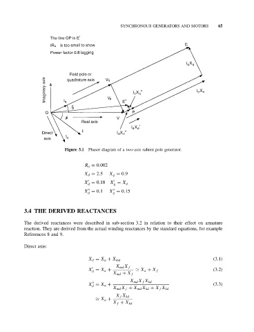
                            Figure 3.1  Phasor diagram of a two-axis salient pole generator.


                                     R a = 0.002
                                     X d = 2.5  X q = 0.9

                                     X = 0.18 X = X q
                                      d          q


                                     X = 0.1   X = 0.15
                                                 q
                                      d
           3.4 THE DERIVED REACTANCES

           The derived reactances were described in sub-section 3.2 in relation to their effect on armature
           reaction. They are derived from the actual winding reactances by the standard equations, for example
           References 8 and 9.

           Direct axis:


                                      X d = X a + X md                                     (3.1)
                                                  X md X f

                                      X = X a +                                            (3.2)
                                        d                   X a + X f
                                                 X md + X f
                                                        X md X f X kd

                                      X = X a +                                            (3.3)
                                        d
                                                 X md X f + X md X kd + X f X kd
                                                  X f X kd
                                           X a +
                                                 X f + X kd
   80   81   82   83   84   85   86   87   88   89   90