
Page 93 - Handbook of Electrical Engineering
P. 93
SYNCHRONOUS GENERATORS AND MOTORS 73
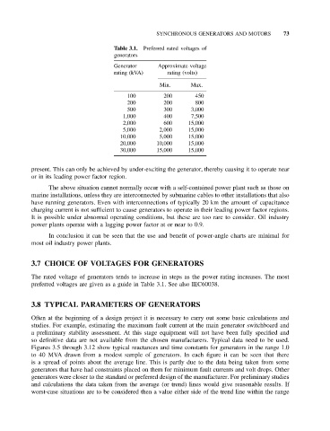
Table 3.1. Preferred rated voltages of
generators
Generator Approximate voltage
rating (kVA) rating (volts)
Min. Max.
100 200 450
200 200 800
500 300 3,000
1,000 400 7,500
2,000 600 15,000
5,000 2,000 15,000
10,000 5,000 15,000
20,000 10,000 15,000
30,000 15,000 15,000
present. This can only be achieved by under-exciting the generator, thereby causing it to operate near
or in its leading power factor region.
The above situation cannot normally occur with a self-contained power plant such as those on
marine installations, unless they are interconnected by submarine cables to other installations that also
have running generators. Even with interconnections of typically 20 km the amount of capacitance
charging current is not sufficient to cause generators to operate in their leading power factor regions.
It is possible under abnormal operating conditions, but these are too rare to consider. Oil industry
power plants operate with a lagging power factor at or near to 0.9.
In conclusion it can be seen that the use and benefit of power-angle charts are minimal for
most oil industry power plants.
3.7 CHOICE OF VOLTAGES FOR GENERATORS
The rated voltage of generators tends to increase in steps as the power rating increases. The most
preferred voltages are given as a guide in Table 3.1. See also IEC60038.
3.8 TYPICAL PARAMETERS OF GENERATORS
Often at the beginning of a design project it is necessary to carry out some basic calculations and
studies. For example, estimating the maximum fault current at the main generator switchboard and
a preliminary stability assessment. At this stage equipment will not have been fully specified and
so definitive data are not available from the chosen manufacturers. Typical data need to be used.
Figures 3.5 through 3.12 show typical reactances and time constants for generators in the range 1.0
to 40 MVA drawn from a modest sample of generators. In each figure it can be seen that there
is a spread of points about the average line. This is partly due to the data being taken from some
generators that have had constraints placed on them for minimum fault currents and volt drops. Other
generators were closer to the standard or preferred design of the manufacturer. For preliminary studies
and calculations the data taken from the average (or trend) lines would give reasonable results. If
worst-case situations are to be considered then a value either side of the trend line within the range