
Page 218 - Handbook of Energy Engineering Calculations
P. 218
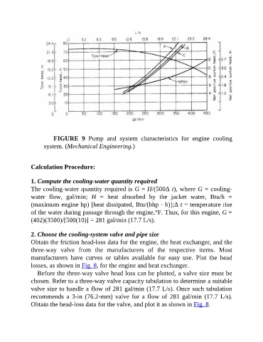
FIGURE  9  Pump  and  system  characteristics  for  engine  cooling

                     system. (Mechanical Engineering.)


               Calculation Procedure:


               1. Compute the cooling-water quantity required
               The cooling-water quantity required is G = H/(500Δ t), where G = cooling-
               water  flow,  gal/min;  H  =  heat  absorbed  by  the  jacket  water,  Btu/h  =
               (maximum engine hp) [heat dissipated, Btu/(bhp · h)];Δ t = temperature rise

               of the water during passage through the engine,°F. Thus, for this engine, G =
               (402)(3500)/[500(10)] = 281 gal/min (17.7 L/s).


               2. Choose the cooling-system valve and pipe size
               Obtain the friction head-loss data for the engine, the heat exchanger, and the

               three-way  valve  from  the  manufacturers  of  the  respective  items.  Most
               manufacturers  have  curves  or  tables  available  for  easy  use.  Plot  the  head
               losses, as shown in Fig. 8, for the engine and heat exchanger.
                  Before the three-way valve head loss can be plotted, a valve size must be

               chosen. Refer to a three-way valve capacity tabulation to determine a suitable
               valve size to handle a flow of 281 gal/min (17.7 L/s). Once such tabulation
               recommends  a  3-in  (76.2-mm)  valve  for  a  flow  of  281  gal/min  (17.7  L/s).
               Obtain the head-loss data for the valve, and plot it as shown in Fig. 8.