Page 436 - Handbook of Energy Engineering Calculations
P. 436
(127.0  mm).  Only  the  shellside  product  must  be  adjusted  since  only  it  is
               affected by the baffle spacing. Therefore, the shell-side factor of the previous
               trial is multiplied by the ratio of the baffle spacing to the 0.6 power:
                                                          0.6
                                                (3.5/5.0)  × 0.367 = 0.296
               The sum of the products (SOP) for this trial is 1.056. The shellside pressure
                                              3
                                                              2
               dropΔP  = 3.9 × (5.0/3.5)  = 11.4 lb/in  (78.5 kPa).
                         a
                  Because we have now reached the point where the assumed design nearly
               satisfies  our  conditions,  tube-layout  tables  can  be  used  to  find  a  standard
               shell-size containing the next increment above 109 tubes. A 10-in-dia (254
               mm) shell in a fixed-tubesheet design contains 110 tubes.

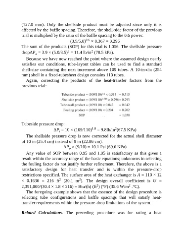
                  Again,  correcting  the  products  of  the  heat-transfer  factors  from  the
               previous trial:


               Tubeside pressure drop:
                                                              1.8
                                                                              2
                                     ΔP  = 10 × (109/110)  = 9.8Ib/in (67.5 KPa)
                                         i
                  The shellside pressure drop is now corrected for the actual shell diameter
               of 10 in (25.4 cm) instead of 9 in (22.86 cm).
                                           ΔP  × (9/10) = 10.1 Psi (69.6 KPa)
                                               o
                  Any  value  of  SOP  between  0.95  and  1.05  is  satisfactory  as  this  gives  a
               result within the accuracy range of the basic equations; unknowns in selecting

               the fouling factor do not justify further refinement. Therefore, the above is a
               satisfactory  design  for  heat  transfer  and  is  within  the  pressure-drop
               restrictions specified. The surface area of the heat exchanger is A = 110 × 12
                                                      2
                                         2
               ×  0.1636  =  216  ft   (20.1  m ).  The  design  overall  coefficient  is  U  =
                                                                                       2
                                                                  2
               2,391,000/(30.4 × 1.8 × 216) = Btu/(h) (ft ) (°F) (35.6 W/m  .°C).
                  The foregoing example shows that the essence of the design procedure is
               selecting  tube  configurations  and  baffle  spacings  that  will  satisfy  heat-

               transfer requirements within the pressure-drop limitations of the system.


               Related  Calculations.  The  preceding  procedure  was  for  rating  a  heat

