
Page 440 - Handbook of Energy Engineering Calculations
P. 440
considered for a process heat exchanger is 5/8 in (15.8 mm) although there
are applications where ½ (12.7 mm), 3/8 (9.5 mm), or even ¼-in (6.4 mm)
tubes are the best selection. Tubes of 1 in (25.4 mm) dia are normally used
when fouling is expected because smaller ones are impractical to clean
mechanically. Falling-film exchangers and vaporizers generally are supplied
with 1½. (38.1 mm) and 2-in (50.8 mm) tubes.
Since the investment per unit area of heat-transfer service is less for long
exchangers with relatively small shell diameters, minimum restrictions on
length should be observed.
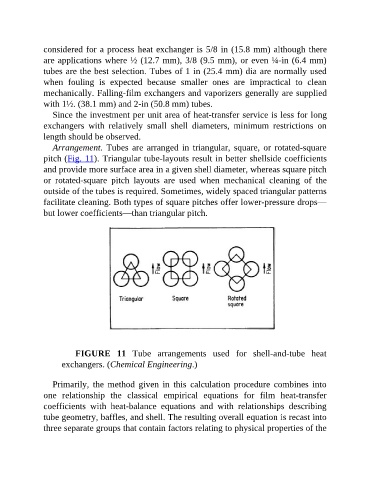
Arrangement. Tubes are arranged in triangular, square, or rotated-square
pitch (Fig. 11). Triangular tube-layouts result in better shellside coefficients
and provide more surface area in a given shell diameter, whereas square pitch
or rotated-square pitch layouts are used when mechanical cleaning of the
outside of the tubes is required. Sometimes, widely spaced triangular patterns
facilitate cleaning. Both types of square pitches offer lower-pressure drops—
but lower coefficients—than triangular pitch.
FIGURE 11 Tube arrangements used for shell-and-tube heat
exchangers. (Chemical Engineering.)
Primarily, the method given in this calculation procedure combines into
one relationship the classical empirical equations for film heat-transfer
coefficients with heat-balance equations and with relationships describing
tube geometry, baffles, and shell. The resulting overall equation is recast into
three separate groups that contain factors relating to physical properties of the