
Page 443 - Handbook of Energy Engineering Calculations
P. 443
D = 1.75 d (nN ) 0.47
o
PT
o
This gives the approximate shell diameter for a packed floating-head
exchanger. The diameter will differ slightly for a fixed tubesheet, U-bend, or
a multipass shell. For greater accuracy, tube-layout tables can be used to find
shell diameters.
The following shows how the design equations are developed for a heat
exchanger with sensible-heat transfer and Reynolds number 10,000 on the
tubeside, and with sensible-heat transfer and cross-flow (flow perpendicular
to the axis of tubes) on the shellside. Equations with other heat-transfer
mechanisms are derived similarly.
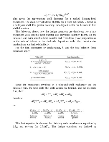
For the film coefficient or conductance, h, and the heat balance, these
equations apply:
Since the resistances involved in a tube-and-shell exchanger are the
tubeside film, the tube wall, the scale caused by fouling, and the shellside
film, then:
ΔT + ΔT +ΔT +ΔT = ΔT M
i
s
w
o
therefore:
ΔT /ΔT + ΔT /ΔT + ΔT /ΔT + ΔT /ΔT = 1
M
M
w
M
s
i
o
M
or:
This last equation is obtained by dividing each heat-balance equation by
ΔT and solving for ΔT /ΔT . The design equations are derived by
M
f
M