
Page 446 - Handbook of Energy Engineering Calculations
P. 446
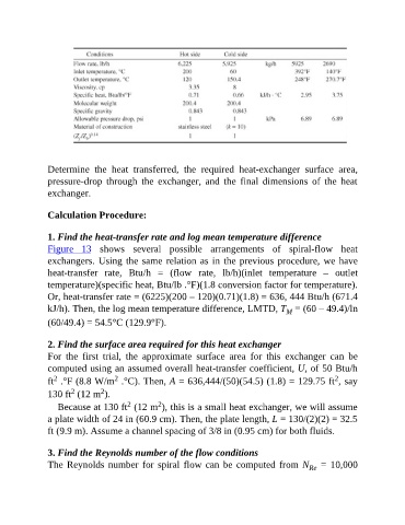
Determine  the  heat  transferred,  the  required  heat-exchanger  surface  area,

               pressure-drop  through  the  exchanger,  and  the  final  dimensions  of  the  heat
               exchanger.


               Calculation Procedure:


               1. Find the heat-transfer rate and log mean temperature difference
               Figure  13  shows  several  possible  arrangements  of  spiral-flow  heat
               exchangers. Using the same relation as in the previous procedure, we have

               heat-transfer  rate,  Btu/h  =  (flow  rate,  lb/h)(inlet  temperature  –  outlet
               temperature)(specific heat, Btu/lb .°F)(1.8 conversion factor for temperature).
               Or, heat-transfer rate = (6225)(200 – 120)(0.71)(1.8) = 636, 444 Btu/h (671.4

               kJ/h). Then, the log mean temperature difference, LMTD, T  = (60 – 49.4)/ln
                                                                                       M
               (60/49.4) = 54.5°C (129.9°F).


               2. Find the surface area required for this heat exchanger
               For  the  first  trial,  the  approximate  surface  area  for  this  exchanger  can  be

               computed using an assumed overall heat-transfer coefficient, U, of 50 Btu/h
                 2
                                                                                                      2
                                    2
               ft  .°F (8.8 W/m  .°C). Then, A = 636,444/(50)(54.5) (1.8) = 129.75 ft , say
                      2
                               2
               130 ft  (12 m ).
                                                 2
                                       2
                  Because at 130 ft  (12 m ), this is a small heat exchanger, we will assume
               a plate width of 24 in (60.9 cm). Then, the plate length, L = 130/(2)(2) = 32.5
               ft (9.9 m). Assume a channel spacing of 3/8 in (0.95 cm) for both fluids.

               3. Find the Reynolds number of the flow conditions
               The Reynolds number for spiral flow can be computed from N   =  10,000
                                                                                              Re