
Page 104 - Handbook of Materials Failure Analysis
P. 104
3 Geometric Nonlinearity 99
Y
p′ q
y cos(q)
q′
VP up y sen(q) v
u
p
y
q
X
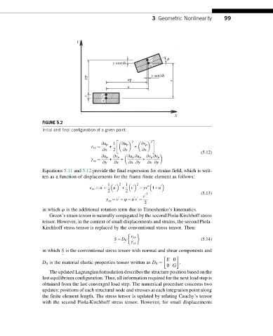
FIGURE 5.2
Initial and final configuration of a given point.
" #
2 2
@u p 1 @u p @v p
ε xx ¼ + +
@x 2 @x @x
(5.12)
@u p @v p @u p @u p @v p @v p
γ ¼ + + +
xy
@y @x @x @y @x @y
Equations 5.11 and 5.12 provide the final expression for strains field, which is writ-
ten as a function of displacements for the frame finite element as follows:
1 2 1 2 0
0
0
0
ε xx ¼ u + u + v yv 00 1+ u
2 2
0 3 (5.13)
v
0 0 0
γ ¼ v φ u v
xy
2
in which φ is the additional rotation term due to Timoshenko’s kinematics.
Green’s strain tensor is naturally conjugated by the second Piola-Kirchhoff stress
tensor. However, in the context of small displacements and strains, the second Piola-
Kirchhoff stress tensor is replaced by the conventional stress tensor. Then:
ε xx
S ¼ D 0 γ (5.14)
xy
¼
in which S is the conventional stress tensor with normal and shear components and
E 0
D 0 is the material elastic properties tensor written as D 0 ¼ .
0 G
¼ ¼
The updated Lagrangian formulation describes the structure position based on the
last equilibrium configuration. Thus, all information required for the next load step is
obtained from the last converged load step. The numerical procedure concerns two
updates: positions of each structural node and stresses at each integration point along
the finite element length. The stress tensor is updated by relating Cauchy’s tensor
with the second Piola-Kirchhoff stress tensor. However, for small displacements