
Page 109 - Handbook of Materials Failure Analysis
P. 109
104 CHAPTER 5 Failure analysis of reinforced concrete structures
The diagonal cracks opening into concrete is directly associated with the main
tensile strain, ε 1 . In the same way, Mazars’ damage criterion is calculated based
on the tensile part of main strain tensor, which allows assuming that stirrups will
be loaded, effectively, only after the beginning of concrete damage.
Therefore, the criterion that defines the beginning of shear reinforcement
mechanical contribution along the load process is given by the damage criterion
expressed in Equation 5.2. According to this approach, a part of shear force dissi-
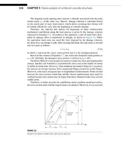
pated by damage effect is transferred to stirrups, as shown in Figure 5.6. While
the equivalent strain does not reach the limit imposed by the damage criterion,
the shear force on stirrups is null. After reaching this limit, the total strain is divided
into two parts as follows:
ε ¼ ε e + ε d (5.24)
in which e represents the elastic strain portion and d is the dissipated portion.
Based on the content of Equation 5.7, one writes the dissipated strain portion as
ε d ¼ Dε. Similarly, the damaged stress portion is defined as σ d ¼ DEε.
The Ritter-M€ orsch’s truss model was used to evaluate the force part transferred to
stirrups. Sanches and Venturini [42] assumed the stress state at the middle of stirrup
to define its strain state. However, when nonlinear mechanical behavior is assumed,
the stresses on stirrups increase from compressed flange toward the tensile flange.
Moreover, it decreases in regions near to longitudinal reinforcements. Points located
between the cross-section central line and the closest reinforcement layer must be
verified because their strains may be larger than those obtained in the cross-section
middle point.
Therefore, to better describe the equilibrium strain condition mentioned earlier,
the cross-section point with the largest strain was adopted. Moreover, it was assessed
s
Elastic prevision Load s d
s e
E
Unload/ s
reload
E
E(1–D)
e
e d e e
FIGURE 5.6
Scheme for stress transfer from concrete to stirrups.