
Page 214 - Handbook of Materials Failure Analysis
P. 214
210 CHAPTER 8 Seismic risk of RC water storage elevated tanks
Table 8.20 Evaluation of the Mass Ratio
Mass of the empty vessel M c 44,327.83 kg
Mass of the supporting system M tower 12,870.00 kg
The ratio M c /M tower 3.44
5.7 QUALITY OF THE NODES
Wedefinethenodesbytheconnectionareasbetweenthestructuralelements,suchasthe
connecting zone “Foundation—support” and the connecting zone “support—tank.”
Among several reasons that are at the origin of failures and damage caused by earth-
quakes,wecitepoordesignand constructionofthenodes intanksbetween resistant ele-
ments. This observation has been demonstrated in previous studies by Masoudi et al.
[17]. The state of connecting zone “Foundation—support” and the connecting zone
“support—tank” is good, without cracks. This parameter is classified as class A.
5.8 SEISMIC ZONE
The tank is located in Sikh Oumedour village, municipality of Tizi Ouzou. The Alge-
rian seismic code classes this municipality as average seismicity zone (zone IIa) (see
Table 8.11). This parameter is classified as class B.
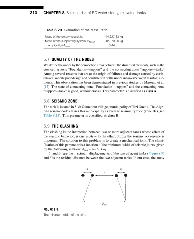
5.9 THE CLASHING
The clashing is the interaction between two or more adjacent tanks whose effect of
the seismic behavior, is one relative to the other, during the seismic occurrence is
important. The solution to this problem is to create a mechanical joint. The classi-
fication of this parameter is a function of the minimum width of seismic joints, given
by the following relation: d min ¼ δ + δ 1 + δ 2 .
δ 1 and δ 2 , are the maximum displacements of the two adjacent tanks (Figure 8.9)
and δ is the residual distance between the two adjacent tanks. In our case, the study
d 1 d 2
d
d min
FIGURE 8.9
The minimum width of the joint.