
Page 213 - Handbook of Materials Failure Analysis
P. 213
5 Case Study 209
D
d
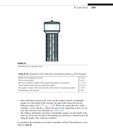
FIGURE 8.8
Different forms of elevated tanks.
Table 8.19 Evaluation of the Geometric Slenderness Ratio λ g of the Support
Height of the supporting system 7.15 m
The buckling length 5.01 m
Minimum moment of inertia of the supporting system cross-section 1.17 m 4
Cross-section of the columns supporting system 0.72 m 2
The gyration radius of the cross-section of the columns supporting system 1.28 m
The geometric slenderness 3.92
• Mass distribution between the vessel and the support must be substantially
regular over the height of the structure, the mass ratio being between the
following values: 0:63 < M c = < 1:33. Where, M c means the mass of the
M tower
container (vessel) and M tower means the mass of the supporting system. In our
case, this criterion is not satisfied (see Table 8.20).
• The stiffness distribution should be substantially regular over the height of the
structure. In our case, the piles of the supporting system have a constant inertia all
along the height. This criterion is satisfied.
In conclusion, the regularity in elevation is partially verified. This parameter is clas-
sified as class B.