
Page 208 - Handbook of Materials Failure Analysis
P. 208
204 CHAPTER 8 Seismic risk of RC water storage elevated tanks
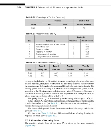
Table 8.12 Percentage of Critical Damping ξ
Frames Shell or Wall
Filling RC Steel RC and Masonry
Light 6 4 10
Table 8.13 Observed Penalties P q
Factor P q
No Criterion q Observed Not Observed
1 Minimum requirements on lines bracing 0 0.05
2 Redundancy plan 0 0.05
3 Regularity in plan 0 0.05
4 Regularity in elevation 0 0.05
5 Quality control of materials 0 0.05
6 Quality control of the execution 0 0.10
Table 8.14 Characteristic Periods T 1 , T 2
Type S 1 Type S 2 Type S 3 Type S 4
Site Rocky Soil Firm Soil Loose Soil Very Loose Soil
T 1 (s) 0.15 0.15 0.15 0.15
T 2 (s) 0.30 0.40 0.50 0.70
corresponding behavior coefficient is determined according to the nature of the con-
stituent materials, the type of construction, the possibility of forces redistribution in
the structure, and deformation elements capabilities in the post-elastic domain. The
bracing system used in the study of this tank is the inverted pendulum system, which,
according to the Algerian seismic code is a system where 50% or more of the mass is
concentrated in the upper third of the structure. Algerian seismic code gives value, to
global behavior coefficient of the tank, R¼2.
X
The quality factor, “Q” is determined by the following relation: Q ¼ 1+ P q .
In this relation, P q means the penalties to remember accordingly that the quality
criterion is satisfied or not (see Table 8.13). For the case of our elevated tank, Q¼1,
because the six penalties are observed.
The characteristic periods T 1 and T 2 are associated with the category of the site,
given in Table 8.14.
We give in the Table 8.15 all the different coefficients allowing drawing the
response spectrum curve (Figure 8.5).
5.3.8 Evaluation of the safety factor
The resulting seismic force at the mass M k is given by the mean quadratic
(Figure 8.6):