
Page 210 - Handbook of Materials Failure Analysis
P. 210
206 CHAPTER 8 Seismic risk of RC water storage elevated tanks
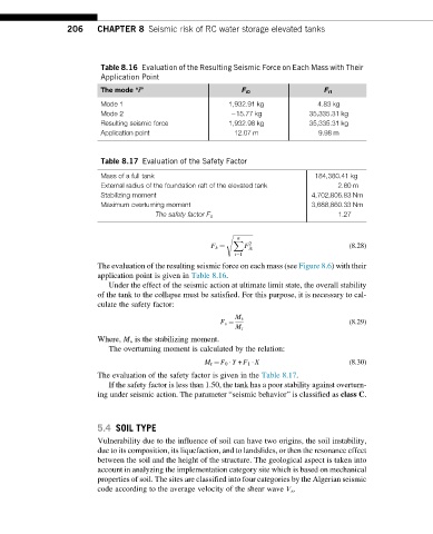
Table 8.16 Evaluation of the Resulting Seismic Force on Each Mass with Their
Application Point
The mode “i” F i0 F i1
Mode 1 1,932.91 kg 4.83 kg
Mode 2 15.77 kg 35,335.31 kg
Resulting seismic force 1,932.98 kg 35,335.31 kg
Application point 12.07 m 9.98 m
Table 8.17 Evaluation of the Safety Factor
Mass of a full tank 184,380.41 kg
External radius of the foundation raft of the elevated tank 2.60 m
Stabilizing moment 4,702,806.83 Nm
Maximum overturning moment 3,688,860.33 Nm
The safety factor F s 1.27
s ffiffiffiffiffiffiffiffiffiffiffiffiffiffi
n
X 2
F (8.28)
F k ¼ ik
i¼1
The evaluation of the resulting seismic force on each mass (see Figure 8.6) with their
application point is given in Table 8.16.
Under the effect of the seismic action at ultimate limit state, the overall stability
of the tank to the collapse must be satisfied. For this purpose, it is necessary to cal-
culate the safety factor:
M s
(8.29)
F s ¼
M r
Where, M s is the stabilizing moment.
The overturning moment is calculated by the relation:
M r ¼ F 0 Y + F 1 X (8.30)
The evaluation of the safety factor is given in the Table 8.17.
If the safety factor is less than 1.50, the tank has a poor stability against overturn-
ing under seismic action. The parameter “seismic behavior” is classified as class C.
5.4 SOIL TYPE
Vulnerability due to the influence of soil can have two origins, the soil instability,
due to its composition, its liquefaction, and to landslides, or then the resonance effect
between the soil and the height of the structure. The geological aspect is taken into
account in analyzing the implementation category site which is based on mechanical
properties of soil. The sites are classified into four categories by the Algerian seismic
code according to the average velocity of the shear wave V s .