
Page 26 - Handbook of Materials Failure Analysis
P. 26
18 CHAPTER 1 Progressive failures of components
Extensive multiple cracking Crack branching
100 µm 20 µm
(a) (b)
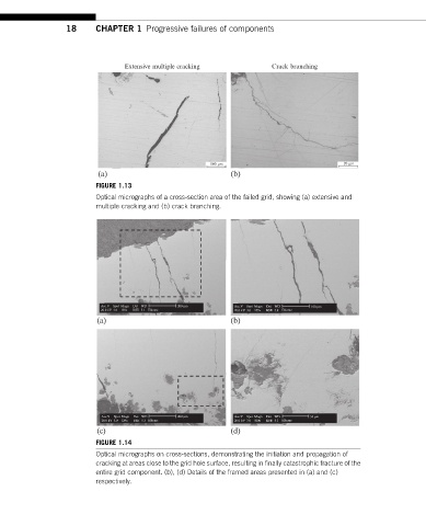
FIGURE 1.13
Optical micrographs of a cross-section area of the failed grid, showing (a) extensive and
multiple cracking and (b) crack branching.
Acc.V Spot Magn Det WD 200 µm Acc.V Spot Magn Det WD 100 µm
20.0 kV 3.0 130x BSE 5.1 Elkeme 20.0 kV 3.0 259x BSE 5.0 Elkeme
(a) (b)
mm
Acc.V Spot Magn Det WD 200 µm Acc.V Spot Magn Det WD 50 µm
20.0 kV 3.0 129x BSE 5.3 Elkeme 20.0 kV 3.0 500x BSE 5.3 Elkeme
(c) (d)
FIGURE 1.14
Optical micrographs on cross-sections, demonstrating the initiation and propagation of
cracking at areas close to the grid hole surface, resulting in finally catastrophic fracture of the
entire grid component. (b), (d) Details of the framed areas presented in (a) and (c)
respectively.